EddyCus® inline – Non-contact Sheet Resistance, Layer Thickness and Electrical Anisotropy Measurement Solutions for Process Control

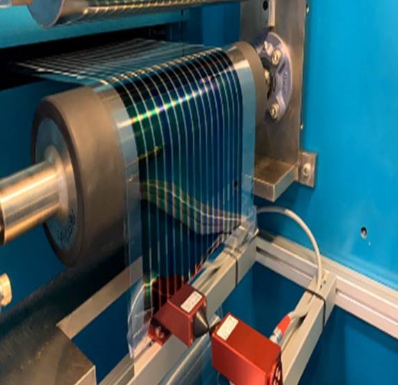
The EddyCus® inline series measures layer properties such as metal layer thickness, sheet resistance, emissivity, residual moisture or grammage in non-contact on various substrates. Relevant substrates are glass, foil, paper, wafer, plastic or ceramic. Monitoring is done by permanent measurement or by trigger events to obtain equidistant results in fast moving coating processes. Monitoring solutions can be implemented either in atmosphere or vacuum conditions. Processes using eddy current technology benefit from high samples rates. Measurement results can be provided for process control systems using customer´s software. Additionally SURAGUS offers the monitoring software EddyCus® EC Control that visualizes, stores and analyses metrology data.


Advantages

  • Non-contact real time measurement
  • High measurement speed up to 1,000 measurements/ sec.
  • Fixed sensor installation or traversing sensor installation
  • Integration of 1 – 99 monitoring lanes per system
  • Process control at atmosphere or in vacuum
  • Measurements very close to the edge of the substrate are possible in many applications
  • Long term stability by temperature compensated measurements in changing environment
  • Large distances to the testing material (e.g. gap of 60 mm / 2.4 inch)
  • Characterization of covered conductive layers or encapsulated substrates
  • Numerous software integrated analysis and statistic functions
  • Easy set up by EddyCus® RampUp software incl. wizard for system calibration
  • Wear- free

Motivation for the Use of Inline Metrology

  • Process control and quality assurance
  • Process time optimization
  • Machine utilization
  • Material usage
  • Productivity
  • Product performance improvement (e.g. high transparency and low resistivity, good emissivity, good barrier properties)
  • Layer homogeneity especially across large substrates widths
  • Predictive maintenance
DISCUSS YOUR MEASUREMENT TASK

Measurement Ranges

  • Sheet resistance: 0.1 mOhm/sq up to 1 kOhm/sq
  • Metal thickness: 2 nm – 2 mm (depending material conductivity)
  • Resistivity: 0.1 mOhm cm – 1 ohm cm
  • Residual moisture (measurement in wet layers by non-contact permittivity measurement)
  • Electrical anisotropy: 0.33 to 3 (higher on request)
  • Correlating properties
    • Grammage: 0.1 to 1,000 g/sqm
    • Emissivity: 0.005 to 0.2

Applications

  • Architectural glass (LowE)
  • Packaging materials
  • Displays and touch screens
  • Photovoltaics (Thin-film and c-Si)
  • Mirror coatings
  • Capacitors
  • OLEDs and LEDs
  • Smart glass
  • Metal layers and wafer metallization
  • De-icing and heating
  • Batteries and fuel cells
  • Coated paper and conductive textiles
  • Graphene layers
  • Antibacterial coatings

Setups

  • Inline R2R
  • Inline S2S
  • Cluster tools
  • Integration into handling areas
  • Transmission and reflection setups

Processes

  • Deposition (PVD, ALD, (PE)CVD, electroplating, printing, spraying etc.)
  • Ablation/ structuring (etching, polishing, laser etc.)
  • Doping/ Implantation
  • Tempering/ Annealing
  • Drying/ Heating

SURAGUS offers inline and offline testing systems to support the achievement of those goals.

Sensor Form Factors (All Measurement Types)

  • Sensor S (many options)
  • Sensor S - Semi-Vac (vacuum only)
  • Sensor M
  • Sensor XS
  • Customized forms (multi sensors)

Interfaces

  • TCP, UDP
  • Modbus
  • CSV, XML
  • Analog, digital
  • Profinet

Environment

  • Atmosphere
  • Vacuum
  • ATEX
  • High temperature version on request

Wiring Setups

  • Control cabinet mounting near sensor positions
  • Direct mounting tool mounting near sensor positions
  • Full sensor integrated hardware
Non-contact sheet resistance measurement of a foil with printed electronics using the SURAGUS EddyCus® TF inline system
Inline sheet resistance measurement of a PV wafer using the SURAGUS EddyCus® TF inline system
Inline sheet resistance measurement of a coated foil using the SURAGUS EddyCus® TF inline system
Two outer sensors test on control line and inner sensor measure on complex structures or additional control line of sheet resistance
5-lane inline sheet resistance measurement of a glass coating process using the SURAGUS EddyCus® TF inline system
DISCUSS YOUR MEASUREMENT TASK

Sheet Resistance

Metal Thickness

Electrical Anisotropy

Wet Coating Thickness and Residual Moisture

Resistivity Conductivity

EddyCus® inline SR / Tool integrated - Non-contact Inline Sheet Resistance Monitoring Solution 

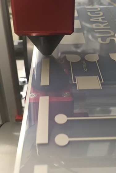
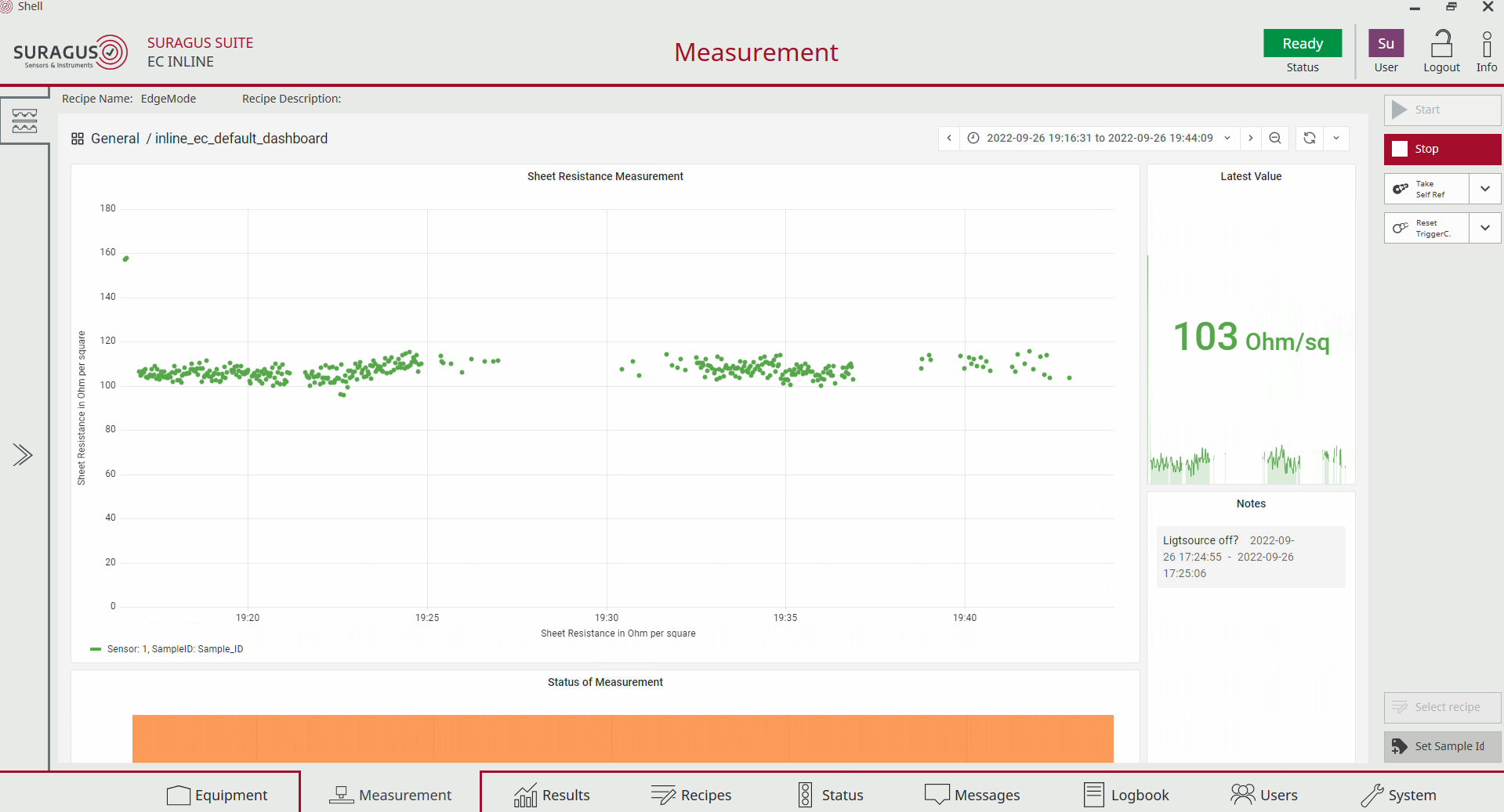
This non-contact sheet resistance monitoring system measures in high speed and non-contact the sheet resistance directly in manufacturing processes. Typical processes involve PVD, CVD, galvanic or conventional deposition processes on wafer, foils, paper, polymers or other substrates. In particular these processes include sputtering, evaporation, epitaxy or plating processes. Additionally, this also involves spraying, slot die coating or electronic printing processes. Furthermore, sheet resistance enhancing processes such as annealing and doping of thin-films or sintering of printed electronics benefit from inline monitoring of the electrical integrity. Oxidation, etching, polishing and also the impact of cleaning and drying processes are also part of the wide application range of this state of the art testing technique. The sheet resistance values are typically transferred to MES systems for quality assurance and particularly for process control.

Data Sheet for EddyCus® inline SR

Measurement technology Non-contact eddy current sensor
Substrates Boules, ingots, wafer, foils, glass, etc.
Measurement gap size 3 / 5 / 10 / 15 / 25 / 50 mm (other upon request)
Number of sensor pairs / monitoring lanes 1 – 99
Sensor sizes (W x L x H) in mm Sensor M: 80 x 100 x 66      Sensor S: 34 x 48 x 117
Conductive layers Metals/ TCOs/ CNTs/ nanowires/ graphene/ grids/ PEDOT/ others
Thickness measurement of metal films (e.g. Al, Ag, Mo, Ag paste) 1 nm – 2 mm (in accordance with sheet resistance) (cf. our calculator)
Other integrated measurements Metal thickness / optical transmittance / density / anisotropy
Environment Ex-vacuo / in-vacuo @ T < 60°C / 140°F (higher on request)
Sample rate 1 / 10 / 50 / 100 / 1,000 measurements per second
Hardware trigger 5 / 12 / 24 V
Interfaces UDP, .Net libraries, TCP, Modbus, analog/digital
  VLSR LSR MSR HSR
  6 decades are measurable by one sensor, but with slightly affected accuracy
For example, a range of 0.001 – 1,000 Ohms with one sensor.
Range [Ohm/sq] 0.0001 – 0.1 0.01 – 10 0.1 – 100 10 – 2,000
Accuracy / Bias ± 1% ± 1 – 3%
Repeatability (2σ) < 0.3% < 0.5%
VLSR – Very Low Sheet Resistance , LSR – Low Sheet Resistance , MSR – Medium Sheet Resistance , HSR – High Sheet Resistance , VHSR – Very High Sheet Resistance


Contact Us

You are welcome to contact our team for

  • Addressing questions
  • Request demo measurements
  • Request online or live demonstrations
  • Request quotations

DISCUSS YOUR MEASUREMENT TASK

EddyCus® inline MT / Tool integrated – Non-contact Inline Metal Thickness Monitoring Solution 

This non-contact metal thickness monitoring system provides immediate feedback for layer deposition and layer removal manufacturing processes. Typical deposition processes include sputtering, evaporation, plating or atomic layer deposition (ALD) e.g. on wafer, foils, glass, ceramics (e.g. PCT), paper, polymers or other substrates. Layer removal processes include polishing (CMP) or etching or laser scribing. The technical concept includes reflective and transmission eddy current sensors and sensor setups. Additionally, a wide range of interface options are supported. 

Data Sheet for EddyCus® inline MT

Measurement technology Non-contact eddy current sensor
Substrates Foil, glass, wafer, etc.
Measurement gap size 3 / 5 / 10 / 15 / 25 / 50 mm (other upon request)
Number of monitoring lanes 1 – 99
Sensor sizes (W x L x H) in mm Sensor M: 80 x 100 x 66      Sensor S: 34 x 48 x 117
Conductive layers Metals
Metal thickness range
Accuracies depend on the selected setup and the type /
conductivity of the metal (e.g. copper, aluminum, silver)
Low             1 – 10 nm; 2 – 5 % accuracy
Standard    10 – 1,000 nm; 1 – 3 % accuracy
High            1 – 100 µm; 0.5 – 3 % accuracy
Metal thickness calibration Direct thickness calibration / sheet resistance conversion
Other integrated measurements Ex-vacuo / in-vacuo @ T < 60°C / 140°F (higher upon request)
Environment Temperature (for integrated temperature drift compensation for long term measurements)
Sample rate 1 / 10 / 50 / 100 / 1,000  measurements/s  (25,000 Hz upon request)
Hardware trigger 24 V (5 or 12 V upon request)
Interfaces UDP, TCP, .Net libraries, Modbus, Profinet, analog/digital, CSV, XML, other
Further available features / other tool configurations Sheet resistance measurement / conductivity / resistivity / anisotropy / emissivity / permeability (beta)


Contact Us

You are welcome to contact our team for

  • Addressing questions
  • Request demo measurements
  • Request online or live demonstrations
  • Request quotations

DISCUSS YOUR MEASUREMENT TASK

EddyCus® inline A / Tool integrated – Non-contact Inline Electrical Anisotropy Monitoring Solution 

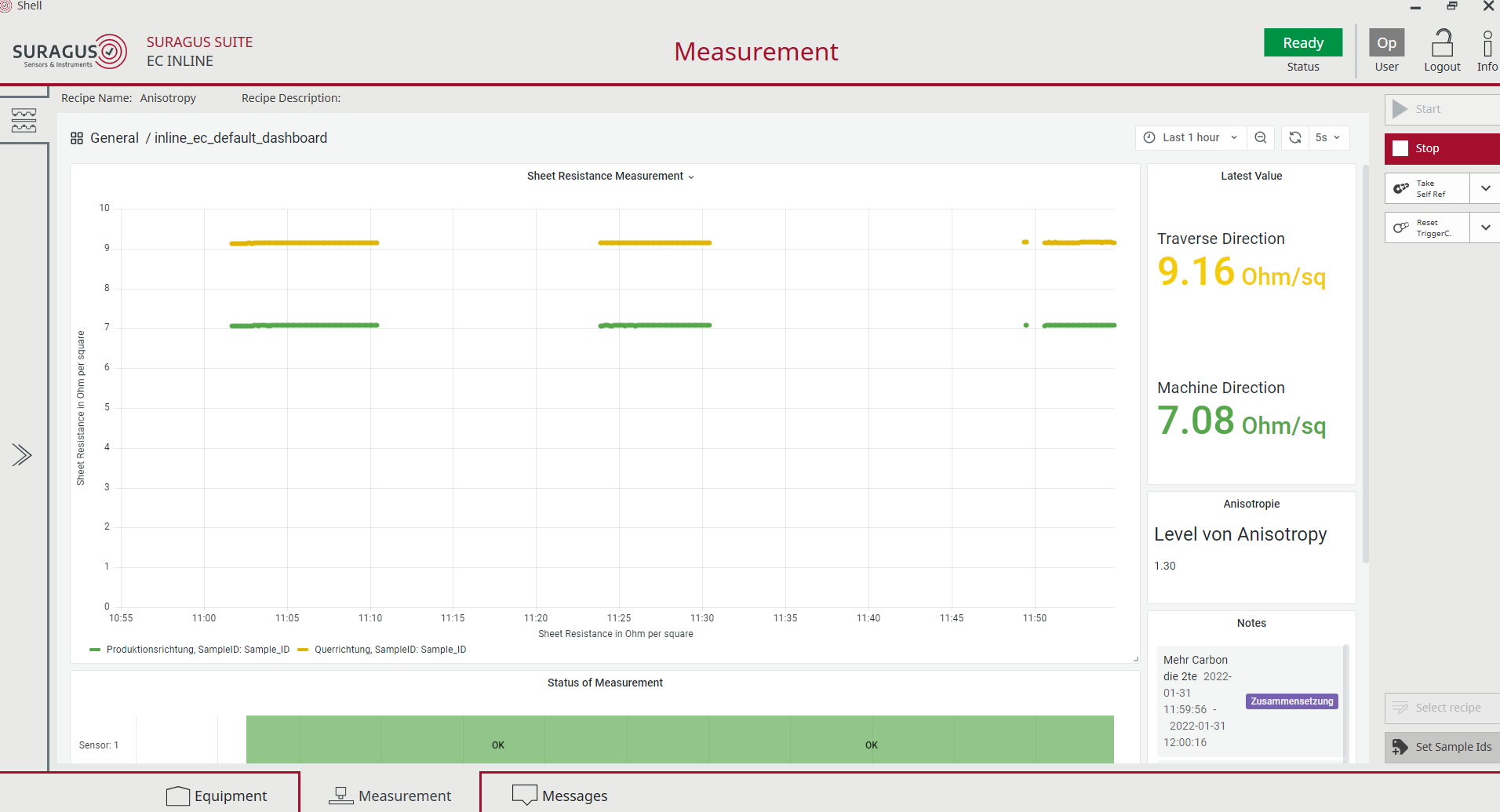
The ability for non-destructive and non-contact inline measurement of electrical anisotropy is a unique capability of SURAGUS. The inline A series induces currents in two or four directions and measures simultaneously the sheet resistance in different directions. The two-direction mode is used for most inline applications. Here the machine direction is the known to be the dominant alignment direction for process reasons and flow of deposition material. If the dominant alignment direction of conductive material is not known, then the four-sensor setup is applied. This sensor series is used for slot die or spray coating, screen printing or spinning processes. Typical materials are Silver nanowires, nanotubes or nanobuds, anisotropic meshes or structures or materials with anisotropic domain sizes or layer (stacks) with advanced current transport functions. The monitors are used to control isotropy or to achieve dedicated anisotropies where current transport is to be optimized in certain directions. In some case those systems are used to measure on structured materials or to identify defects.

Materials

  • Nanowires
  • Nanotubes / Nanobuds
  • Regular metal meshes
  • Materials with egg shaped domains
  • Stacked multilayer systems with advance current transport functions

Measurement Results

  • Absolute / relative anisotropy
  • Dominant current transport directions
  • Sheet resistance in machine direction
  • Sheet resistance in traversing directions (cross-web)

Data Sheet for EddyCus® inline A

Measurement technology Non-contact eddy current sensors with directed current induction
Substrates Foils, glass, wafer, etc.
Measurement gap size 5 / 10 / 15 / 25 / 50 / 75 mm
Number of sensor pairs / monitoring lanes 1 – 99
Sensor sizes (W x L x H) in mm Sensor M: 80 x 100 x 66      Sensor S: 34 x 48 x 117
Sheet resistance range 0.01 – 1,000 Ohm/sq; 1 to 5 % accuracy
Anisotropy range (TD/MD) 0.33 – 3 (larger upon request)
Environment Ex-vacuo/ in-vacuo @ T < 60°C / 140°F (higher upon request)
Sample rate 1 / 10 / 50 / 100 / 1,000 measurements per second
Hardware trigger 5 / 12 / 24 V
Interfaces UDP, .Net libraries, TCP, Modbus, analog/digital
Further available features Metal thickness, optical transmittance and reflectance (OEM)


Contact Us

You are welcome to contact our team for

  • Addressing questions
  • Request demo measurements
  • Request online or live demonstrations
  • Request quotations

DISCUSS YOUR MEASUREMENT TASK

EddyCus® inline HF / Tool integrated – Non-contact Inline Wet Coating Thickness and Residual Moisture Monitoring Solution 

The HF series utilizes high frequency (HF) electromagnetic fields that interact with layers utilizing different effects. Those systems are used to analyze dielectrical and electric properties. Applications include the measurements such as residual moisture and layer thicknesses of wet coatings. Processes include spray, slot die coating, curtain coating and many more wet deposition processes. Additionally drying and calendaring processes can be controlled.

Testing Parameter

  • Residual Moisture
  • Material composition (conductive vs dielectric vs magnetic elements)
  • Wet coating thickness

Data Sheet for EddyCus® inline HF

Measurement technology Non-contact high frequency eddy current sensor
Substrates Foils, glass, pipes, various containers and transport items
Max. sample thickness/ sensor gap Transmission setup: 3 – 50 mm (defined by the thickest sample)
Reflection setups: infitive (only surface area is analyzed) 
Number of sensor pairs / monitoring lanes 1 – 99
Sensor sizes (W x L x H) in mm Sensor M: 80 x 100 x 66      Sensor S: 34 x 48 x 117
Measurement types Wet thickness (µm) / weight (g/m²) / drying status (%) / conductivity (MS/m) /
resistivity (mOhm cm) / permeability (H/m) Beta / permittivity (F/m) Beta
Measurement range / accuracy Depends on the measurement task and the material composition and test object volume.
Please consult with the SURAGUS team
Further available measurements Sheet resistance, metal thickness, anisotropy, optical transparency, reflection, haze
Environment Ex-vacuo
In-vacuo
ATEX on request
T < 60°C (higher upon request)
Sample rate 1 / 10 / 50 / 100 / 1,000 measurements per second
Hardware trigger 5 / 12 / 24 V
Interfaces UDP, .Net libraries, TCP, Modbus, analog/digital


Contact Us

You are welcome to contact our team for

  • Addressing questions
  • Request demo measurements
  • Request online or live demonstrations
  • Request quotations

DISCUSS YOUR MEASUREMENT TASK

EddyCus® inline RM / Tool integrated – Non-contact Inline Resistivity and Conductivity Monitoring Solution 

The EddyCus® inline RM sensors measure the resistivity or conductivity or related parameters in automated handling or processing tools and manufacturing lines. Materials include semiconductors such as Si, SiC, GaAs, GaN, SiSiC and metals and alloys or other conductive materials. Applications in PV or semiconductor industry include wafer, boule or ingot characterization. Even further, temperature measurement of wafer, metals and metal sheets can be obtained by exploiting the correlation of temperature to resistivity. Bulk or volume materials are characterized with reflective mode sensors. Various penetration depth levels can be achieved by sensor and frequency variation. Further applications include integrity imaging of structured films or printed electronics on 3D shapes.

Materials

  • Semiconductor (Si, SiC, GaAs, GaN, SiSiC)
  • Metals and Alloys

Application:

  • Resistivity / Conductivity (Wafer, Boule, Puck level)
  • PN characterization
  • Temperature measurement of hot conducting materials (e.g. Aluminium sheets)
  • Structure imaging
  • monitoring of laser removal processing (mobile friendly glass, bird friendly glass)
  • Distance measurement to low and high conductive materials

Processes

  • Wafer quality monitoring by Float zone (FZ) and Czochralski growth (CZ) manufacturing
  • Semiconductor modification by implantation or annealing
  • PN junction manufacturing processes
  • Cooing and heating process monitoring

Sensor Setups

  • Reflection mode (one sensor element) for 2D and 3D shapes
  • Transmittance mode (two sensor elements) with known or measured material thickness

Data Sheet for EddyCus® inline RM

Measurement technology High frequency eddy current sensor
Penetration depth 10 µm to 10 mm (depending on conductivity and measurement frequency 10 kHz to 50 MHz cf. technology page)
Spot size Various sensors are available. Coil size is 875 µm to 100 mm
Substrates Wafer, metals, alloys, ceramics, plastics etc.
Measurement gap size 5 / 10 / 15 / 25 / 50 / 75 mm
Number of sensor 1 – 99
Sensor sizes (W x L x H) in mm Sensor M: 80 x 100 x 66      Sensor S: 34 x 48 x 117
Materials Semiconductors, metals, alloys, conductive polymers, conductive ceramics
Measurement mode Single side reflection mode or transmittance mode with total thickness measurement
Conductive layers Metals/ TCOs/ CNTs/ nanowires/ graphene/ grids/ PEDOT/ others
Resistivity range 0.1 – 1,000 mOhm·cm
Conductivity range 0.01 – 65 MS/m ()
Environment Ex-vacuo/ in-vacuo @ T < 60°C / 140°F (higher upon request)
Sample rate 1 / 10 / 50 / 100 / 1,000 measurements per second
Other integrated measurements Metal thickness / optical transmittance / density / anisotropy
Hardware trigger 5 / 12 / 24 V
Interfaces UDP, .Net libraries, TCP, Modbus, analog/digital

Contact Us

You are welcome to contact our team for

  • Addressing questions
  • Request demo measurements
  • Request online or live demonstrations
  • Request quotations

DISCUSS YOUR MEASUREMENT TASK

SURAGUS Eddy Current Sensors

SURAGUS offers several sensor geometries with the same functionalities. The different types are dedicated to address given space requirements. Sensor S and XS have a small footprint but require more height. This is often used for measurements between rollers and in tight productions lines. Sensor M requires less height and is often used when there are no size restrictions. The Semi-Vac sensor is a sensor type where one part of the sensor is inside of the vacuum and one side is outside of the vacuum. This has advantages for high vacuum applications. All sensor options are described in more detail below.

SURAGUS provides four types of sensors:

Choose the tab of your preferred sensor type below:

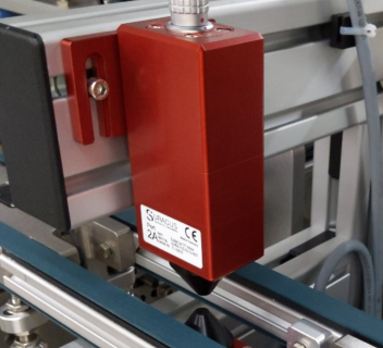
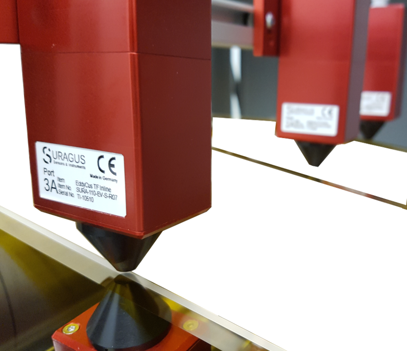
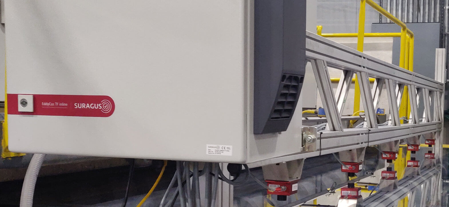
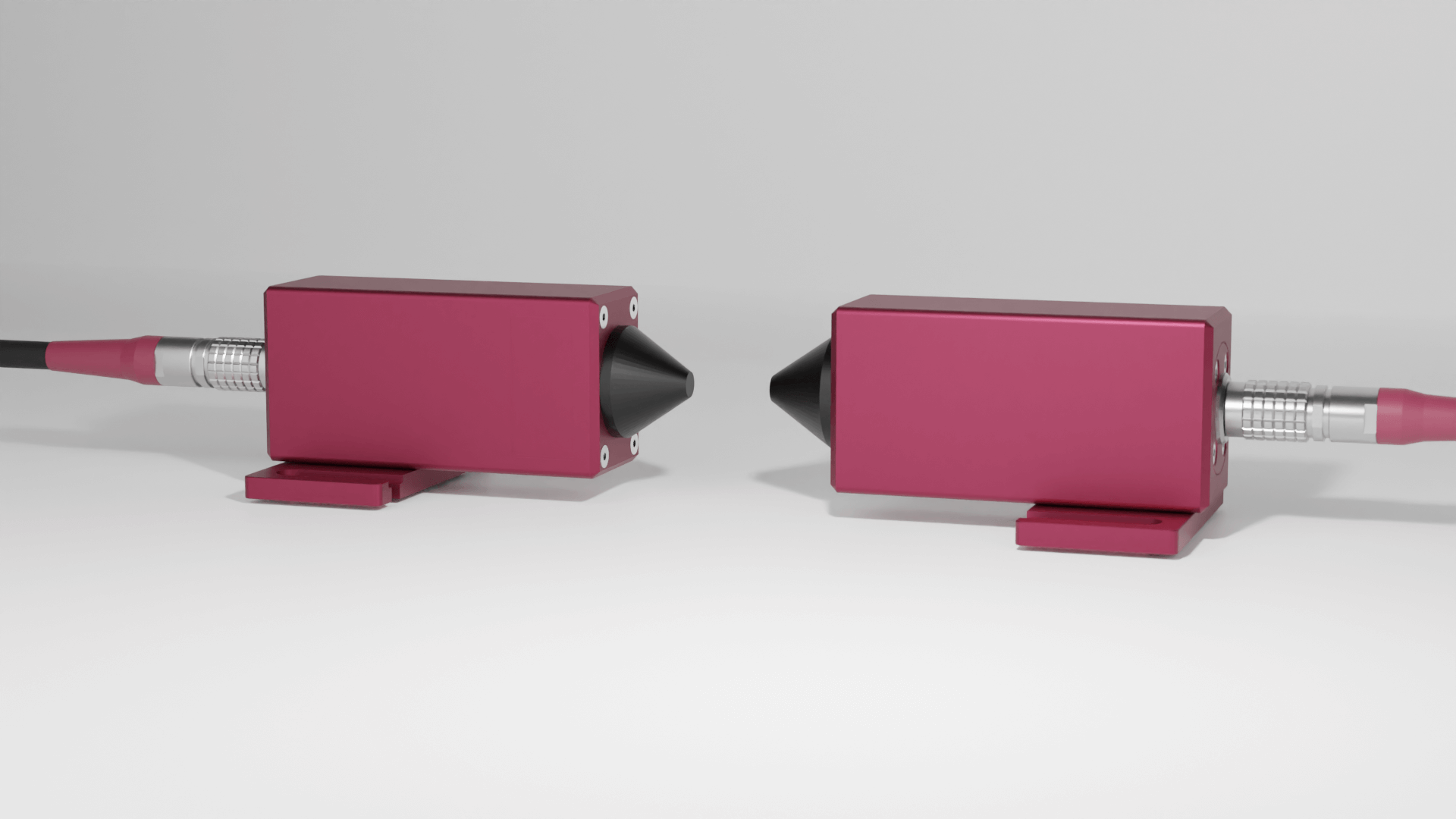
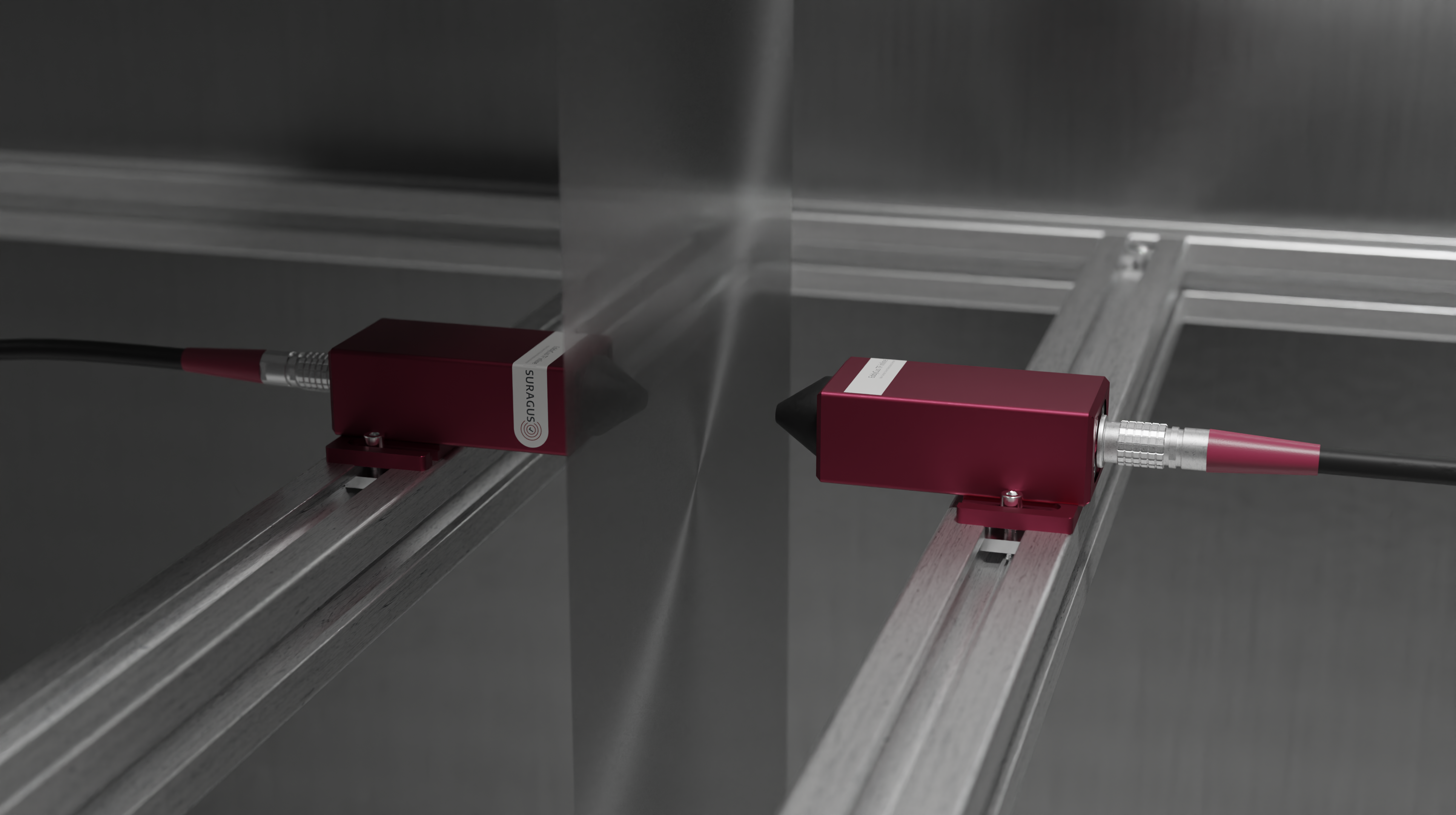
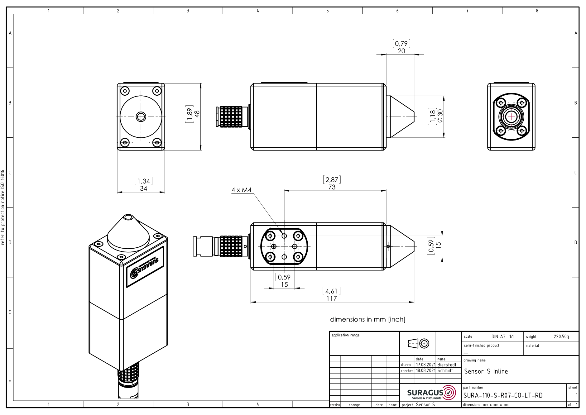
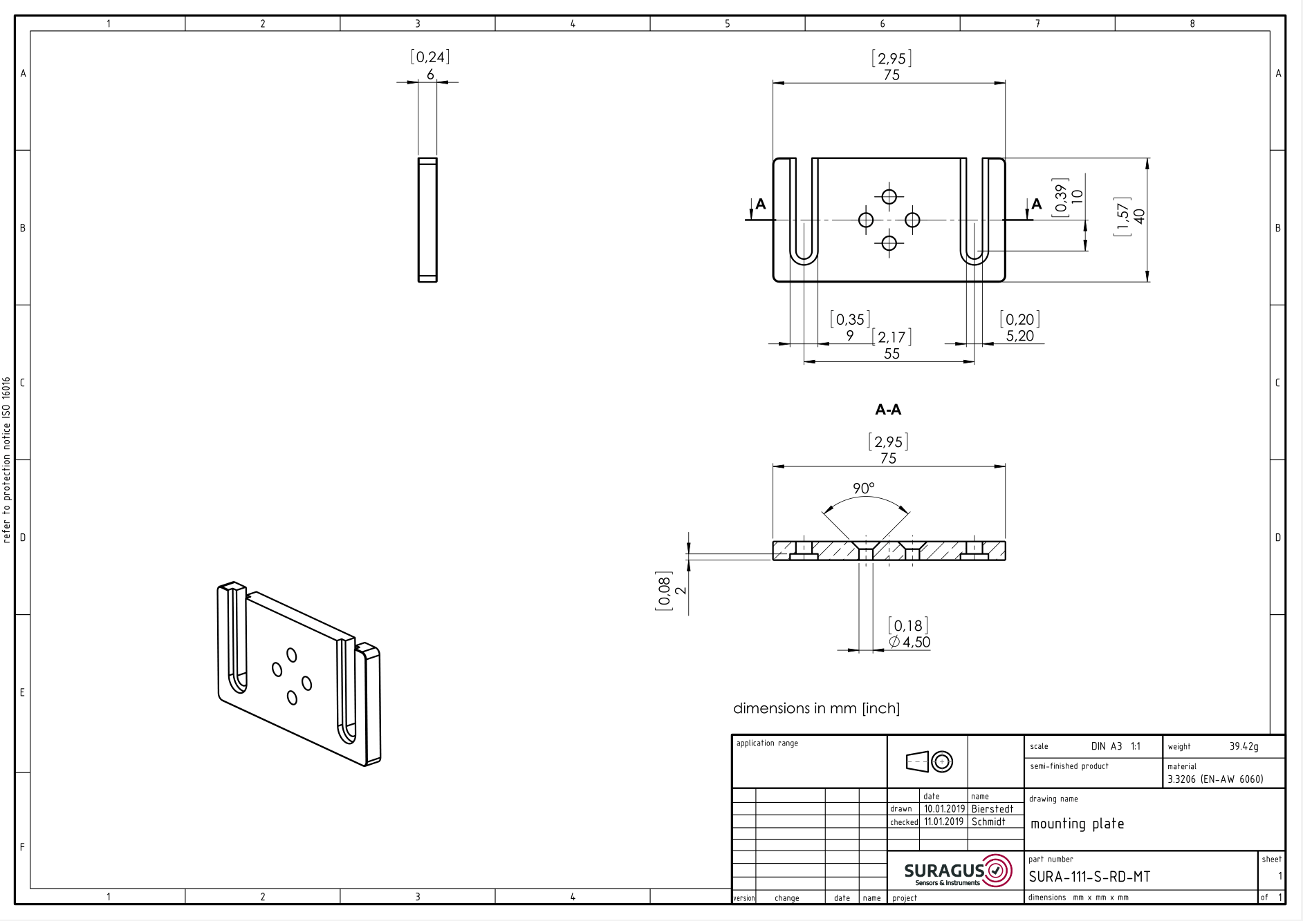
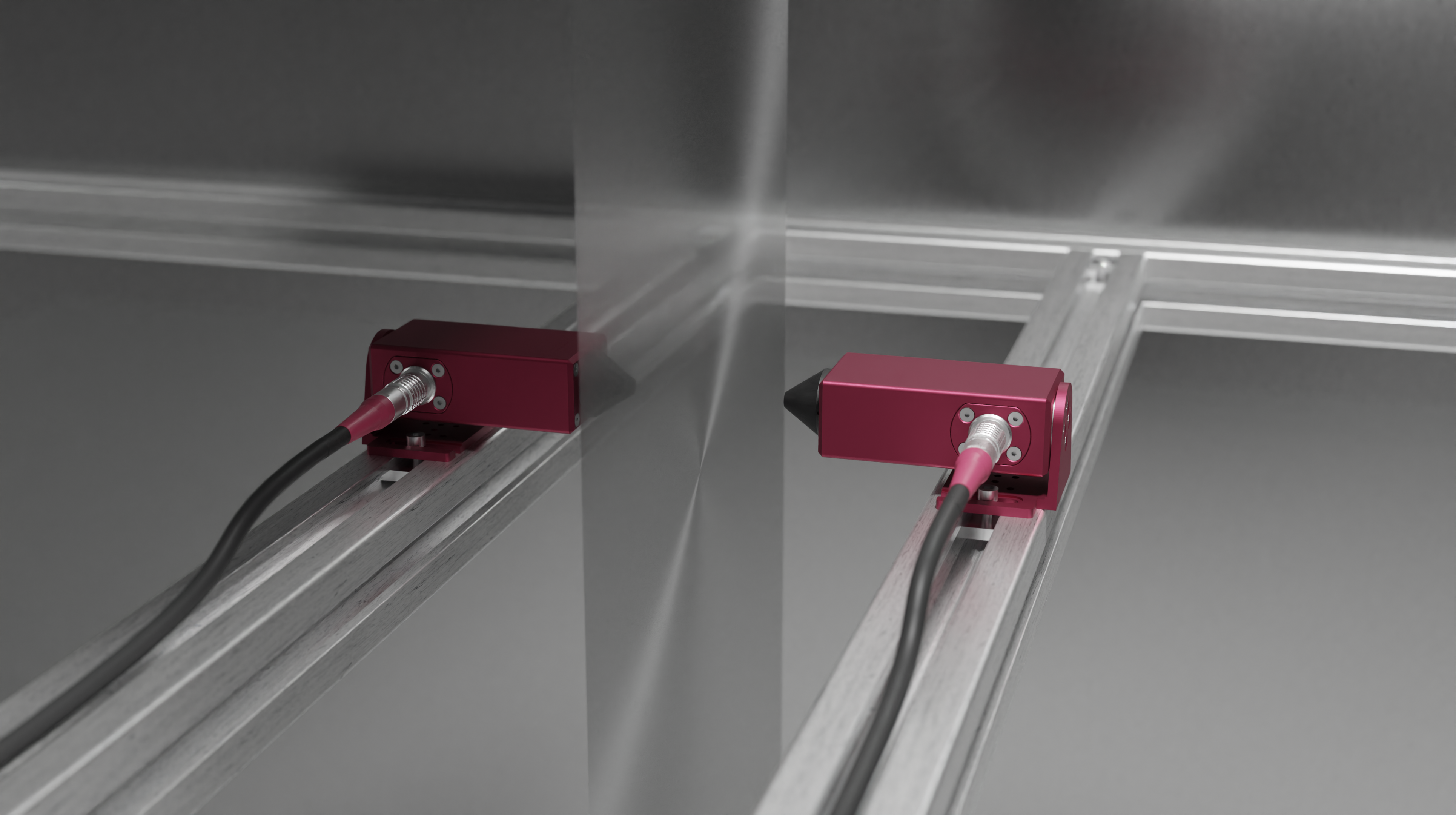
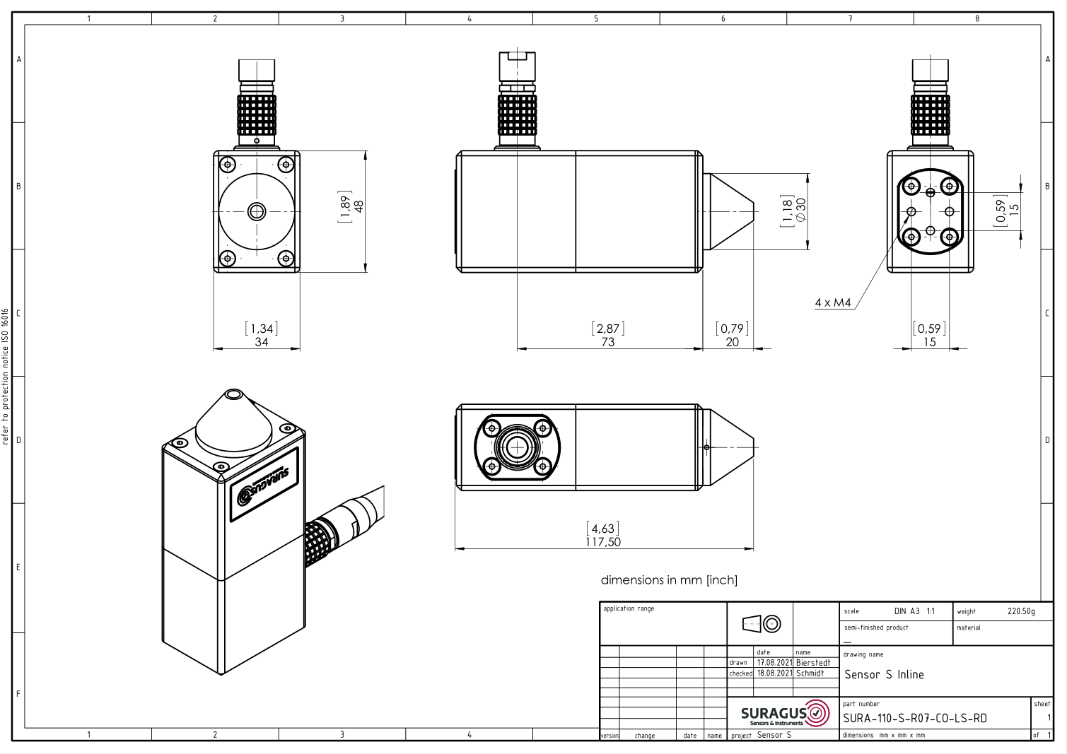
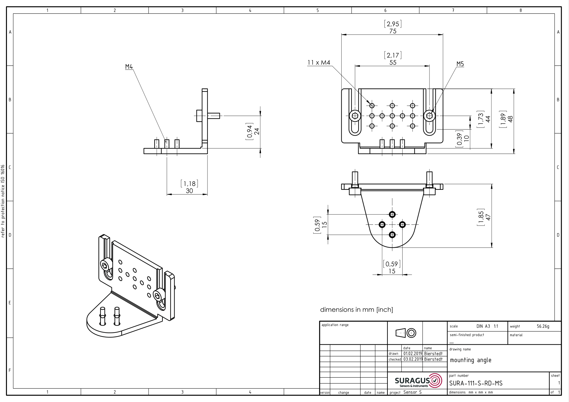
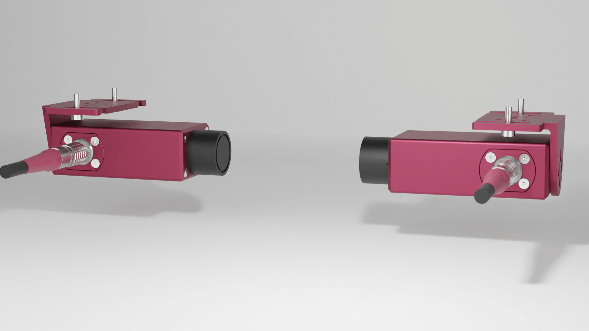
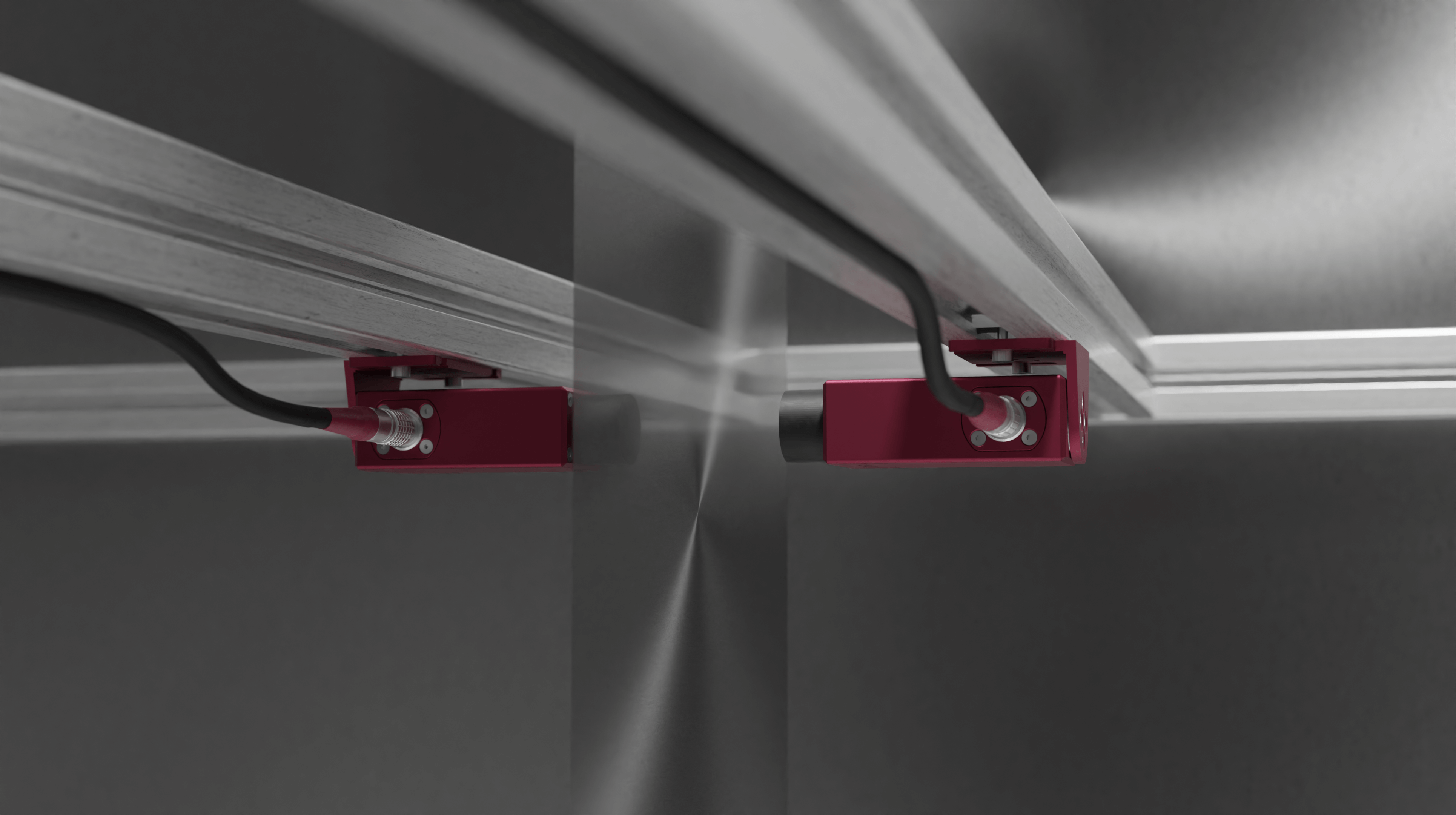
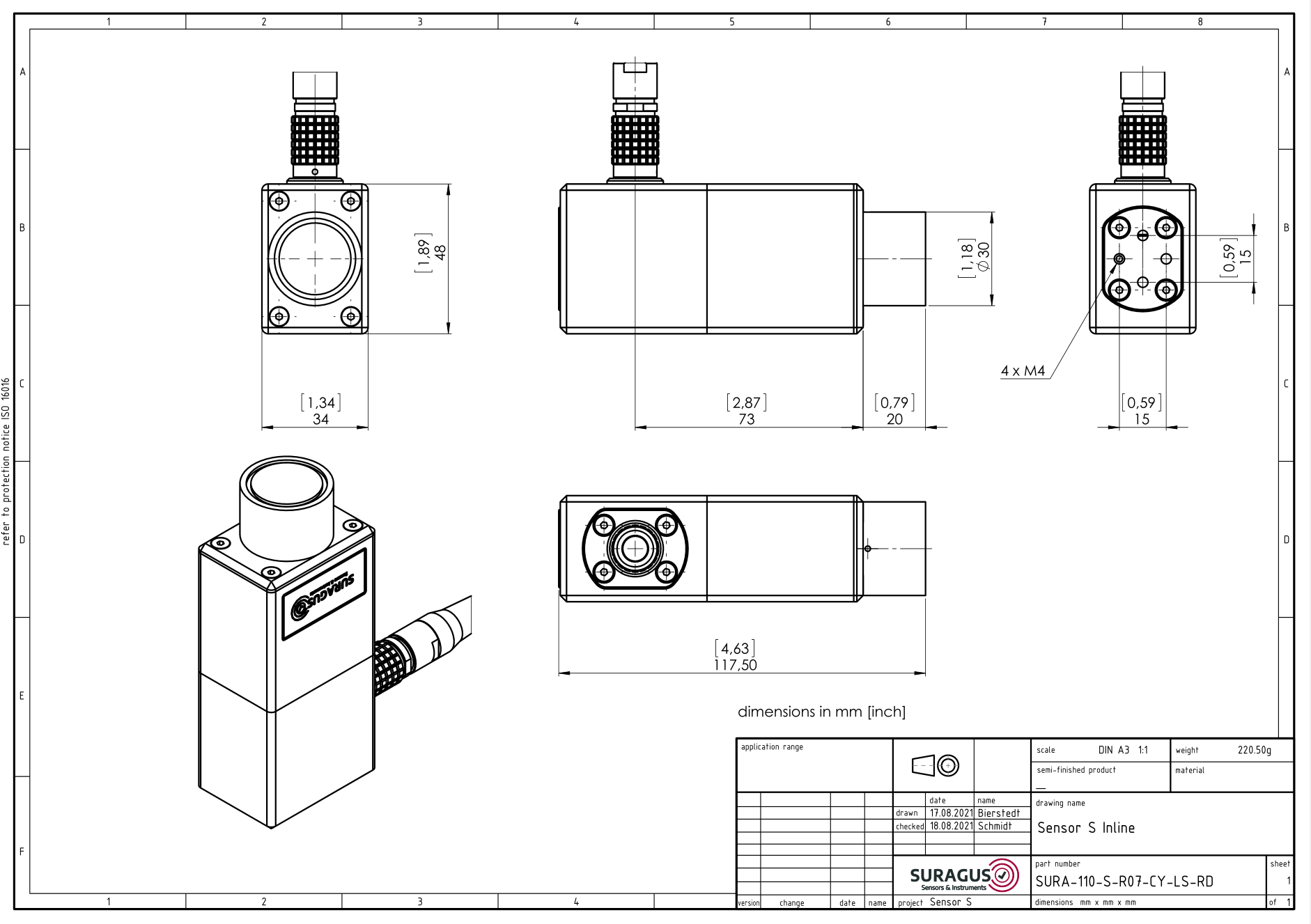
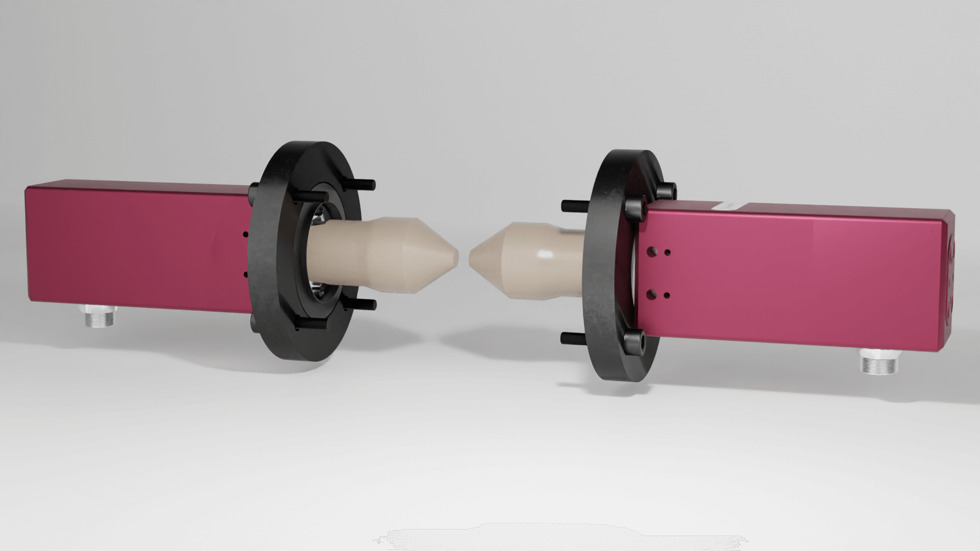
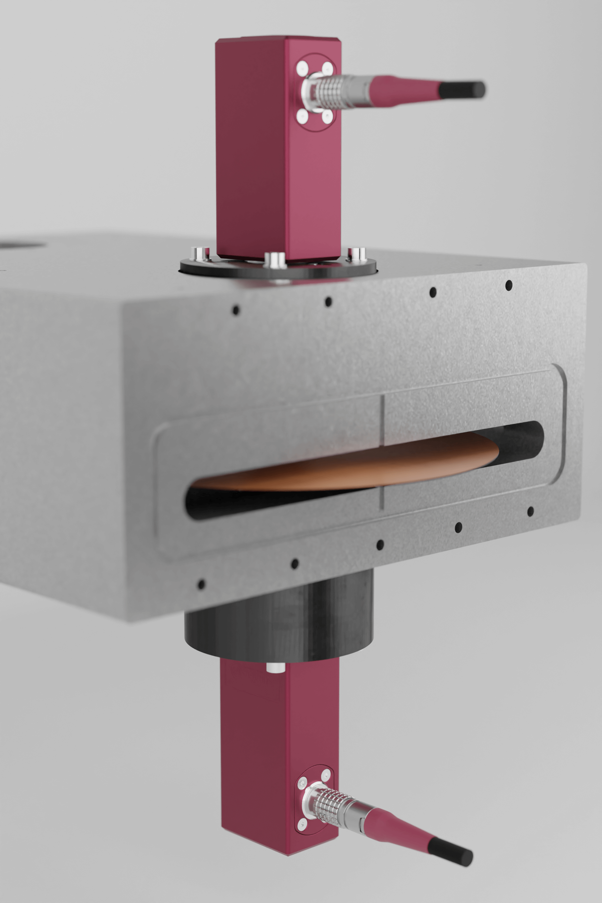
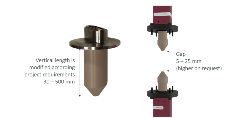
The S Sensor (S for small) is the most popular sensor type at SURAGUS. Its dimensions are 34 x 48 x 117 (WLH) and it fits into narrow spaces between rollers or other geometries within the integration area. There are two type of cord exits (top and side) which support a neat integration and optimal wiring. SURAGUS offers two types of mounting brackets that enable various types of mountings (top, side …) and facilitate an easy sensor height adaption. This sensor is available for non-vacuo or vacuo applications.

Mounting

  • Top/bottom mounting
  • Vertical and horizontal

Size

  • Length 48 mm
  • Width 34 mm
  • Height 117 mm

Environment

  • Ex-vacuo
  • In-vacuo
  • ATEX on request

Download STEP-Files

STEP-files and Drawings Download Form

Please enter your email address. Afterwards SURAGUS will immediately share a link for downloading the 3D step files and drawings for the selected sensor type.

Picture Gallery of Mounting Brackets

Picture Gallery of the Sensor S

Examples

Inline measurement Sensor S with top exit
Inline measurement Sensor S with top exit in production evironment
SURA-110-S-R07-CO-LT-RD.png
SURA-111-S-RD-MT.png
Inline measurement Sensor S with side exit
Inline measurement Sensor S with side exit in production environment
SURA-110-S-R07-CO-LS-RD.png
SURA-111-S-RD-MS.png
Inline measurement Sensor S with side exit and mounting on the bottom
Inline measurement Sensor S with side exit and mounting on the bottom in a production site
SURA-110-S-R07-CY-LS-RD.png
SURA-111-S-RD-MS.png

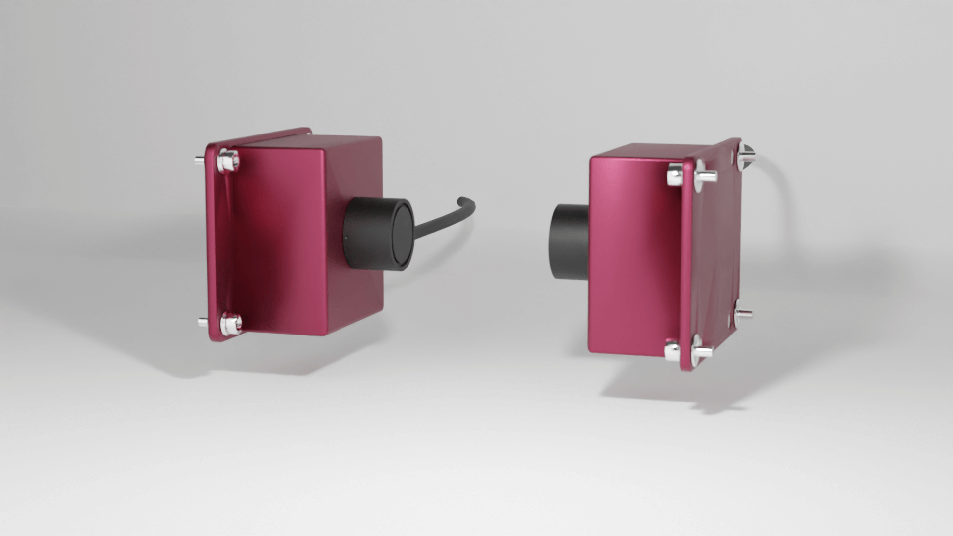
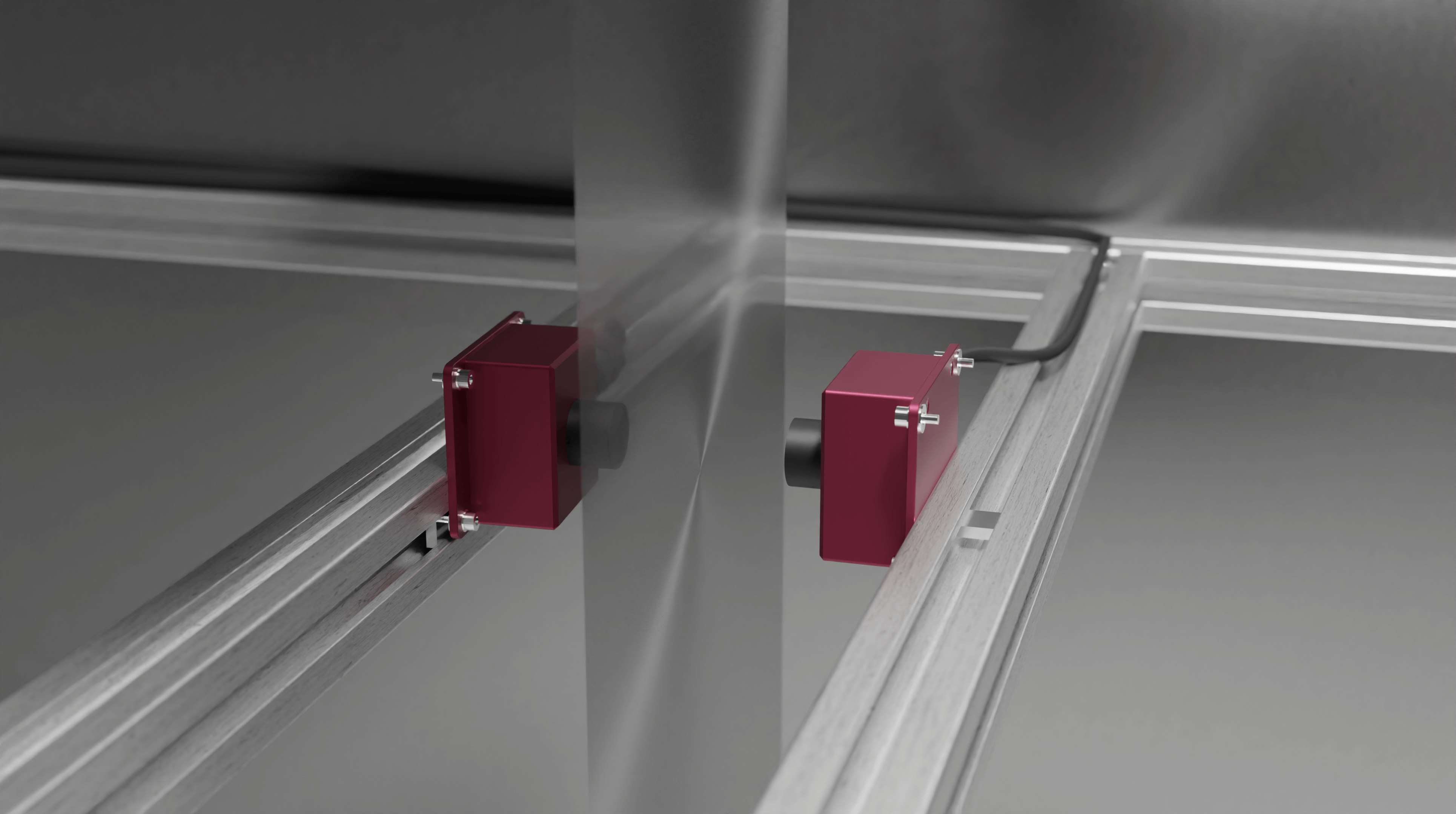
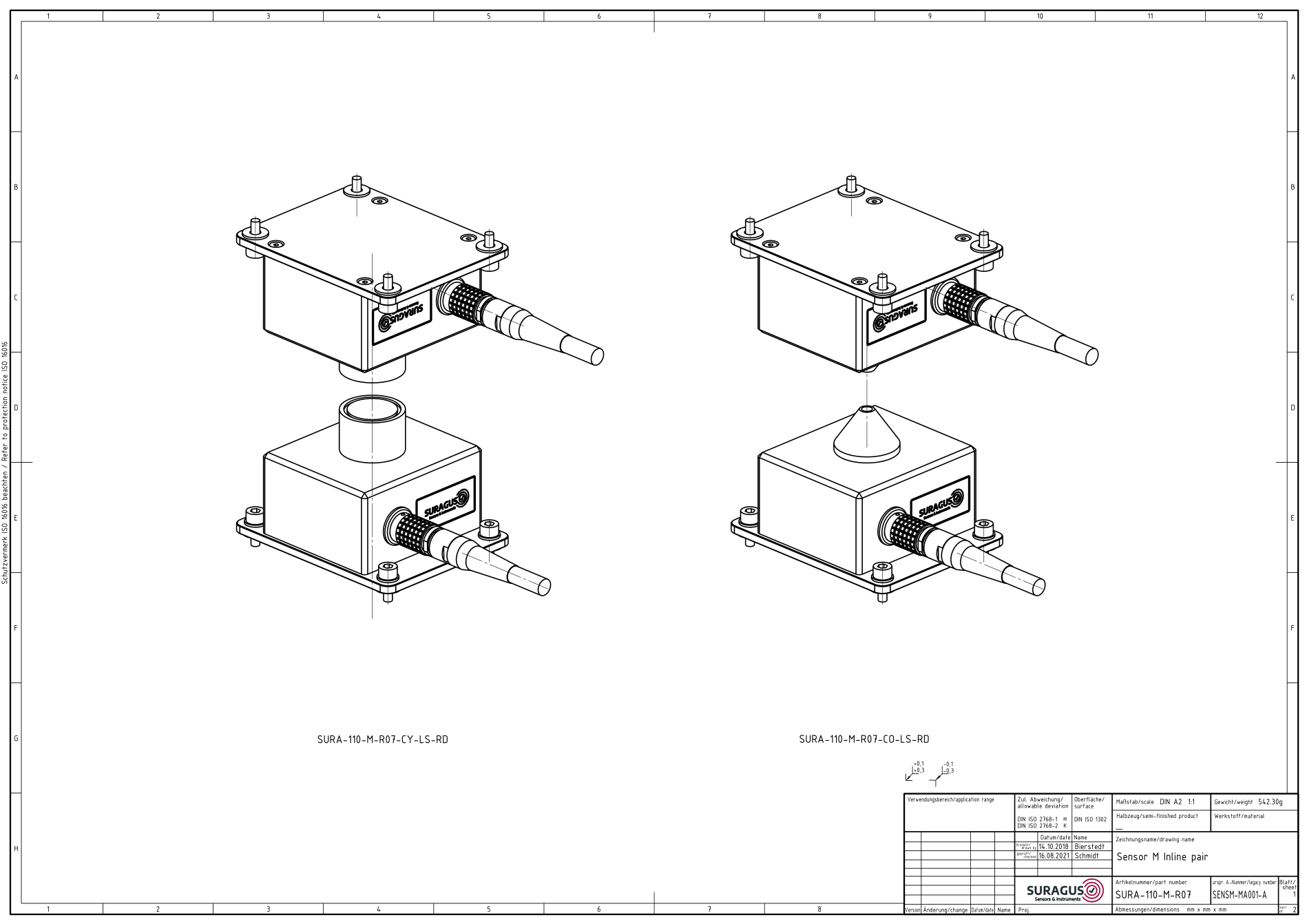
The Sensor M is requires less vertical space compared with the S sensor and is often used for spaces with low space below and above the integration area. This sensor is available for non-vacuo or vacuo applications. This housing type is available for reflective and transmission mode setups. The probe size can be adjusted to cater coil sizes from 1 to 100 mm.

Mounting

  • Top/bottom mounting
  • Vertical and horizontal

Size

  • Length 80 mm
  • Width 100 mm
  • Height 65 mm

Environment

  • Ex-vacuo
  • ATEX on request
Download STEP-Files

STEP-files and Drawings Download Form

Please enter your email address. Afterwards SURAGUS will immediately share a link for downloading the 3D step files and drawings for the selected sensor type.

Picture Gallery of the Sensor M

Side view of the non-contact eddy current "Sensor M" for sheet resistance, metal layer thickness and resistivity measurement
Side view of the non-contact eddy current "Sensor M" for sheet resistance, metal layer thickness and resistivity measurement in production environment
Drawing_Sensor_M_SURA-110-M-R07.jpg

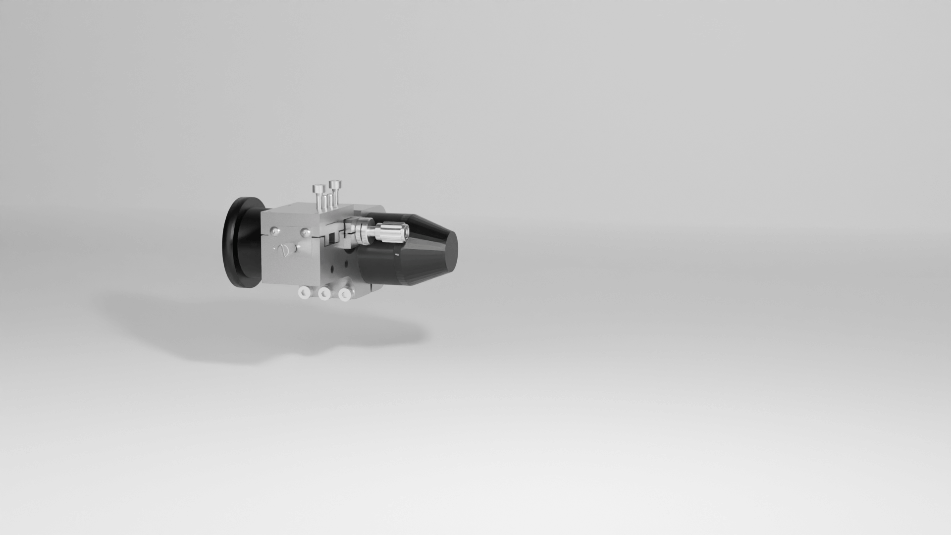
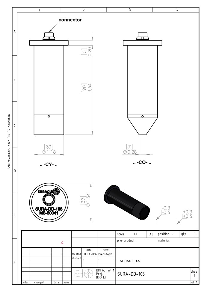
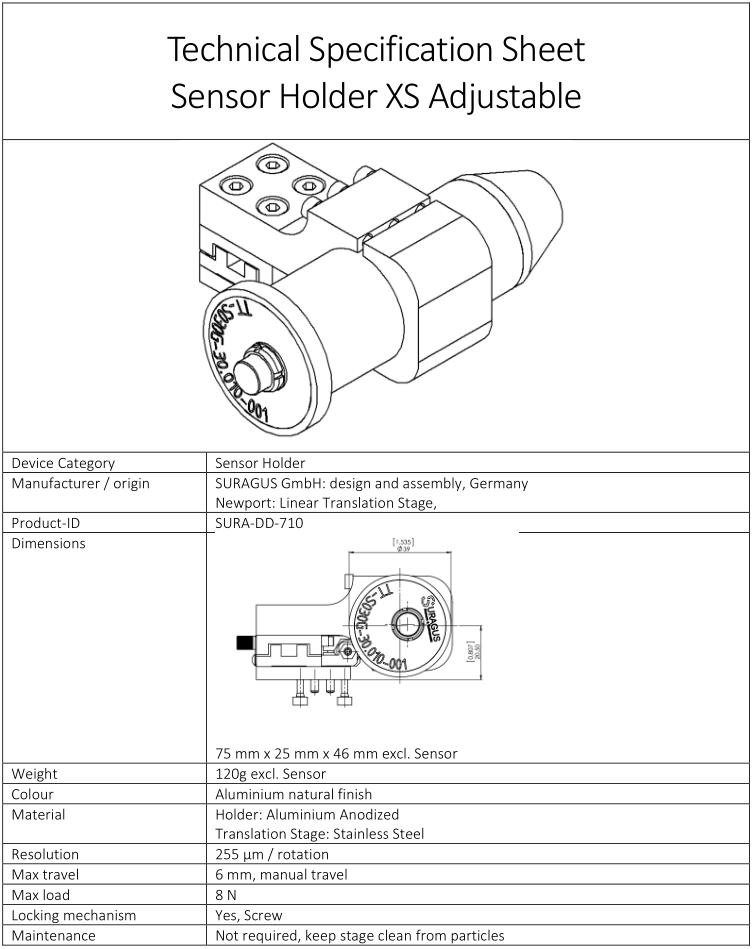
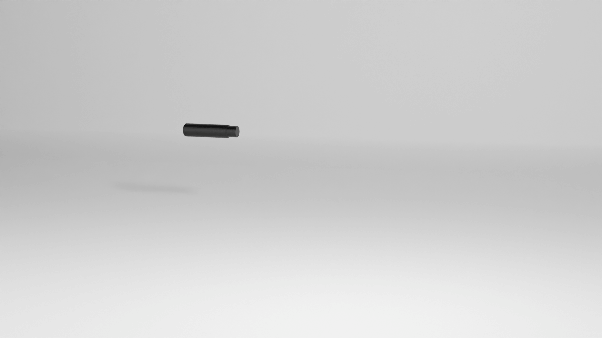
The Sensor XS is an eddy current sensor operating in reflection mode. It is usually used for integration into 3D robots or scanning systems operating in reflectance mode. Its diameter is only 30 mm.

Mounting

  • Top/bottom mounting
  • Vertical and horizontal
  • Precisely adjustable over a range of 6 mm

Size

  • Diameter 30 mm
  • Height 95 mm

Environment

  • Ex-vacuo
  • ATEX on request
Download STEP-Files

STEP-files and Drawings Download Form

Please enter your email address. Afterwards SURAGUS will immediately share a link for downloading the 3D step files and drawings for the selected sensor type.

Picture Gallery of the Sensor XS

Inline measurement in reflection mode with the Sensor XS for sheet resistance, metal layer thickness and resistivity measurement.
Inline measurement in reflection mode with the Sensor XS for sheet resistance, metal layer thickness and resistivity measurement with holding mechanism that is adjustable in µm steps
Drawing of Sensor XS - SURA-DD-105 .jpg
technical specification sheet sensor holder XS adjustable.png

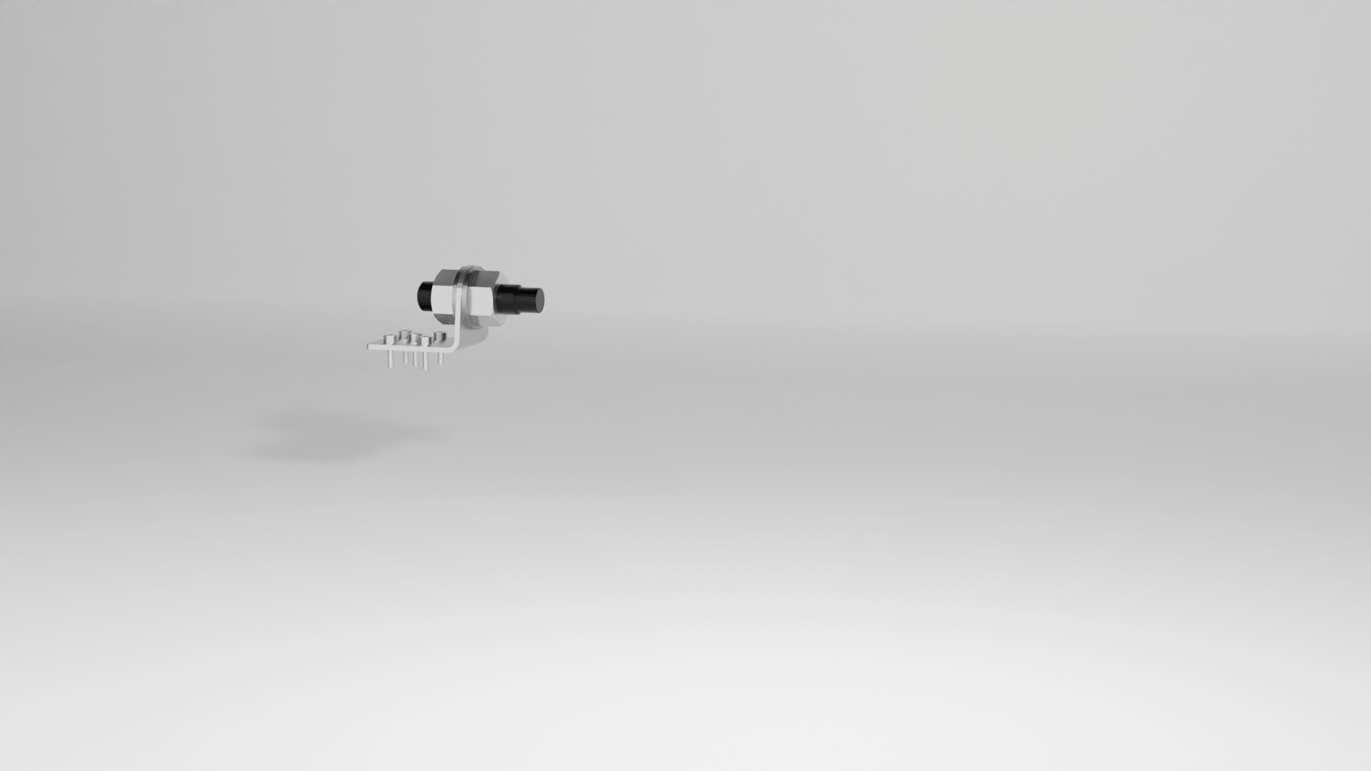
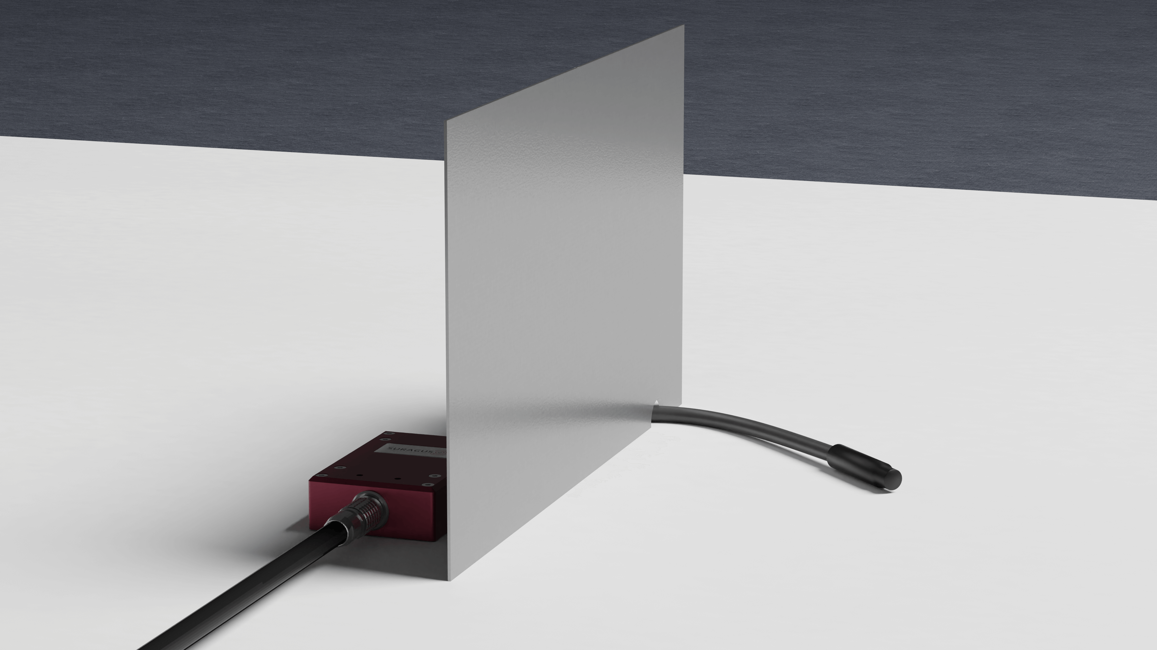
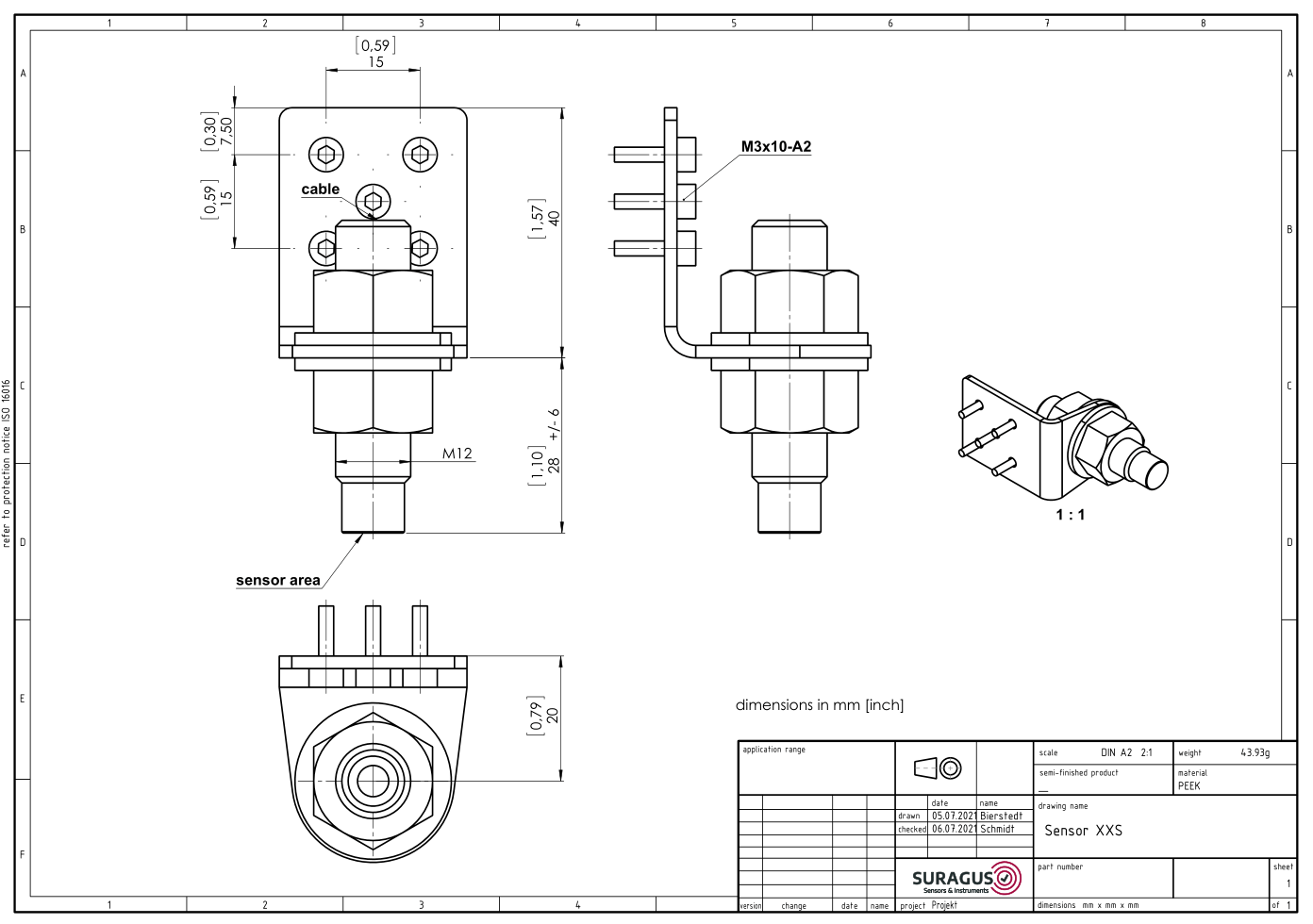
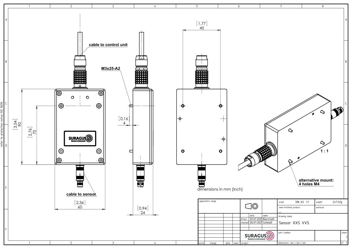
The Sensor XXS is the smallest sensor solution dedicated for measurement environments with little space. The sensor has an diameter of 12 mm only and a height of 50 mm. This sensor is available for non-vacuo or vacuo applications. This housing type is available for reflective and transmission mode setups. This sensor is also available as a high temperature version. This sensor is typically applied when sensor S or sensor M do not fit or the sensors need to cope with high temperatures.

Mounting

  • Top/bottom mounting
  • Vertical and horizontal

Size

  • Diameter 12 mm
  • Height 50 mm

Environment

  • Ex-vacuo
  • ATEX on request
Download STEP-Files

STEP-files and Drawings Download Form

Please enter your email address. Afterwards SURAGUS will immediately share a link for downloading the 3D step files and drawings for the selected sensor type.

Picture Gallery of the Sensor XXS

Inline measurement Sensor XXS is our smallest eddy current inline sensor for very small spaces and also available for high temperature environments
Sensor XXS with Mounting.png
Inline measurement Sensor XXS with heating plate is a eddy current sensor for high temperature areas
Drawing Sensor XXS.png
Drawing Sensor XXS with PreAmp.png

The Sensor S-SemiVac is suitable for vacuum tools with limited space requirements. It also minimizes the volume of and components in the vacuum. There are several versions available. The shown version measures through a KF40. Other options measure through PEAK or Glass windows. Please consult with the SURAGUS team. This sensor is available for reflective and transmission mode setups.

Mounting

  • Top/bottom mounting
  • Vertical and horizontal

Size

  • Length 80 mm
  • Width 100 mm
  • Height 65 mm

Environment

  • Semi-vacuo
  • ATEX on request
Download STEP-Files

STEP-files and Drawings Download Form

Please enter your email address. Afterwards SURAGUS will immediately share a link for downloading the 3D step files and drawings for the selected sensor type.

Picture Gallery of the Sensor S-SemiVac

In-situ measurement for deposition processes in vacuum chambers with the Sensor S SemiVac
Sensor S SemiVac with vacuum chamber for the in-situ measurement of PVD process
S-SemiVac.PNG

The ASU Sensor is mostly used for in-vacuo measurement.

Mounting

  • Top/bottom mounting
  • Vertical and horizontal

Size

  • Length 80 mm
  • Width 34 mm
  • Height 112.5 mm

Environment

  • Ex-vacuo
  • In-vacuo
  • ATEX on request
Download STEP-Files

STEP-files and Drawings Download Form

Please enter your email address. Afterwards SURAGUS will immediately share a link for downloading the 3D step files and drawings for the selected sensor type.

Picture Gallery of the Sensor ASU

Measurement Beams and Bridge Types

Requirements and Options for Measurement Bridges

  • In-vacuo / ex-vacuo
  • Fix or variable sensor positioning
  • Available space at place of integration
  • Freestanding autarkic measurement bridge vs. integrated solutions
  • Mounting opportunities to existing structure (conveyer belt, deposition chamber)

Types of Mounting Bridges

  • Beam integration
  • Frame integration
  • Conveyer integration
  • Free standing
  • Ultra Wide

Bridge Types in Vacuo

  • In-vacuo
  • n Sensor positions
  • Minimizes required space in tide machines
  • Effective cord wiring
  • Length and mounting plates are customized according available space and mounting points

Bridge Types Free Standing

  • Ex-vacuo
  • n Sensor positions
  • Electrical and mechanical independent

Software and Interfaces

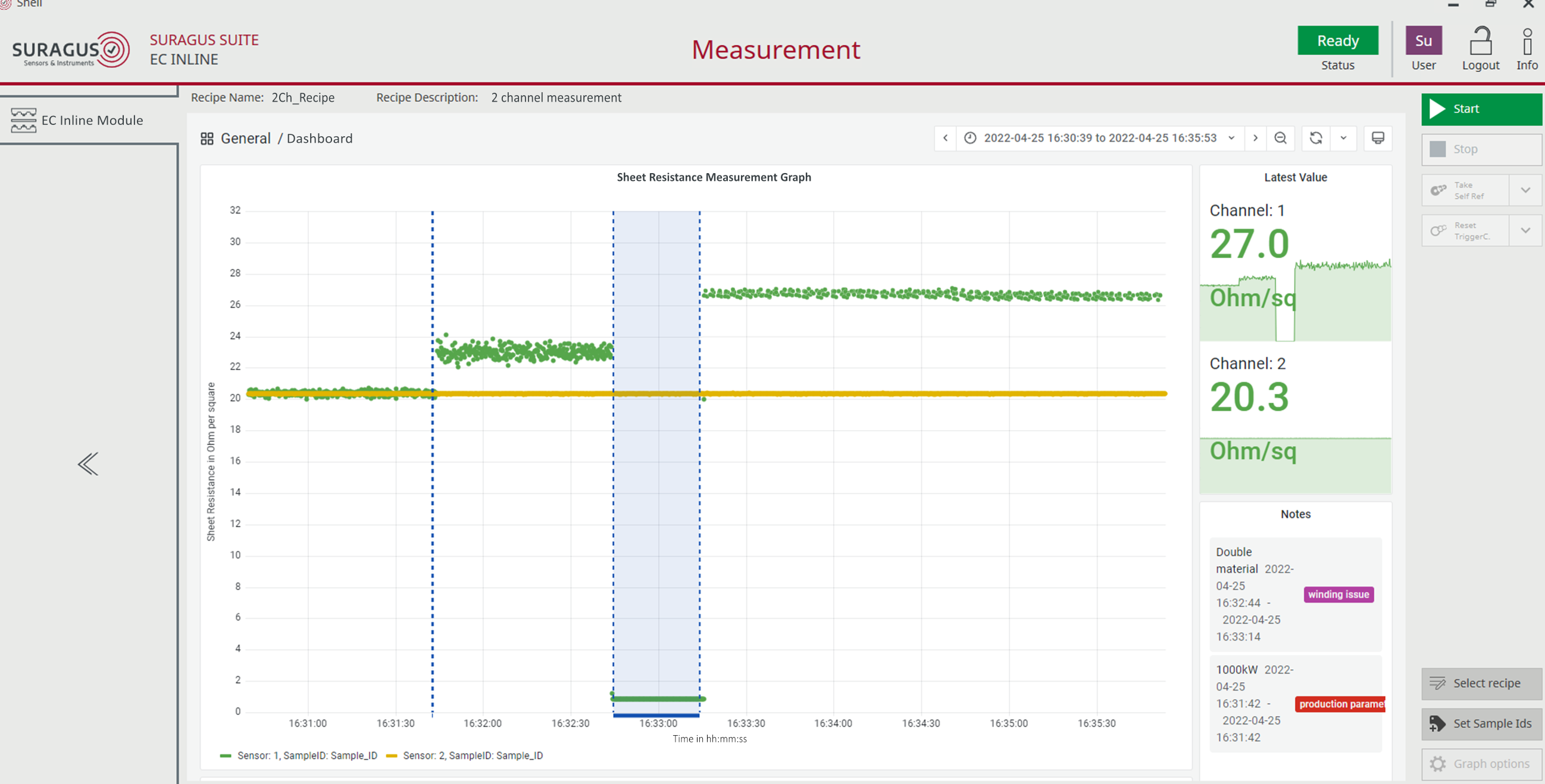
Inline monitoring systems can be implemented into MES or other high level manufacturing software. SURAGUS offers independ sensor systems using comprehensive software.

  • Direct implementation of sensors using .Net libraries (documentation, project examples, sensor mockup are provided pre setup and test)
  • Data transmission via standardized protocols (e.g. Modbus) or TCP/IP based protocols
  • Data access via OPC by KEPServer with ODBC client
  • Analog or digital communication via I/O module(s), individual  parameterizable
  • Data access via database mapping
  • Additional solutions on request

SURAGUS provide three software solutions:

  1. The EC inline Control software is a self developed analysis tool
  2. The OEM and developer kits is a SDK and data post processing SDK that allows you to design a customized software for the specific needs accordung to your business
  3. Direct PLC integration to control the manufactoring process

    EC inline Control Software

    • Graphical live view (different time windows, from 1 minute to 24h)
    • Analysis view (data selection from database, statistics)
    • Sorting by time, distance, roll number, barcode or Data Matrix code.
    • Mode for extending and adapting the calibration
    • Parameterization dialog of I/O modules for analog and digital data transmission as well as the parameterization of alarms in case of over/underrun of threshold values
    • Automatic and manual data export (csv, txt, xls, ...)
    • Automatic database cleaning
    Sheet resistance measurement graph shown by the inline measurement software
    Sheet resistance measurement graph shown by the inline measurement software while measuring wafers
    Level of the electrical anisotropy calculated with sheet resistance values shown by the inline measurement software
    Sheet resistance measurement graph shown by the inline measurement software. 5 lanes on a LowE glass.
    SURAGUS EC Inline Measurement

    Software Developer Kits and Post Processing Kits

    Software Developer Kit - EC CU

    • EC CU SDK
      • EC CU Class Libraries (single files)
      • EC CU Class Libraries (nugget package)
      • Developer Documentation (html / chm)
      • User Manual
      • Sample Project – VS 2015 project 
      • Calibration and Calibration validation 
    • EC CU Emulator
      • Emulator App as Windows Installer
      • User Manual
    • EC CU Setup Tool 
      • Customizing of the processing pipe line
    • Trigger Modes
      • Free Running
      • Gate Mode (high / low)
      • Edge Mode (raising / falling)
      • One Measurement on High / Low

    SURAGUS Post Processing Library – EC PP

    Functions / Algorithms

    • Specimen recognition within data stream
      • Position of edges and center
      • Size
      • Value
      • Determination of minima and maxima (value, position) 
      • Determination of specimen length
    • References
      • Compensation of hardware variations and drift
        • SP, 1D, 2D
    • Edge-Effect-Compensation
      • Direct method
      • Reference method 
    • Further application specific functions

    Direct PLC Integration

    SURAGUS offers serveral hardware options for PLC integration incl. sensors with full digitalization at sensor level and direct PLC communicaton.

    Interfaces

    • Modbus
    • UDP
    • TCP XML
    • Profinet
    • OI module
    • Ethernet IP (available soon)
    • EtherCAT (available soon)

    Trigger mode

    • Free Running
    • Gate Mode (high / low)
    • Edge Mode (raising / falling)
    • One Measurement on High / Low

    Other points

    • User and roll management

    Contact

    For product requests contact us by using the

    SEND EMAIL

    For a prompt and informative response, please describe your measurement task (material, sample dimensions, expected measurement range) and provide your phone number.

    Consent to data processing

    By sending this form, I permit SURAGUS GmbH to process my data for contacting me. For more details see our Imprint & Privacy Policy