For product requests contact us by using the
- Contact formular,
- Email (sales@suragus.com) or
- Phone (+49 351 32 111 520).
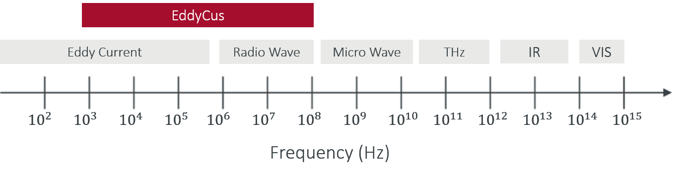
The eddy current testing method utilizes local conductivity variations for the characterization of quality characteristics such as thickness, sheet resistance, material homogeneity or other physical changes in the sample of investigation. The complex eddy current signal contains various information about the test material, which can be separated in many cases with simple or complex algorithms. The applied powerful eddy current electronics offers a wide frequency range from 10 kHz to 100 MHz that is utilized to achieve different sensitivities and penetration depth depending on the application. All SURAGUS products are offered with an user-friendly software for fast real-time evaluation.
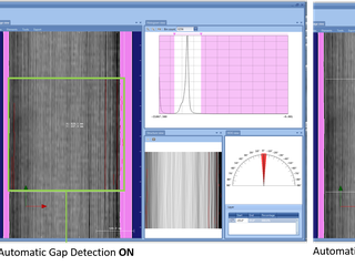
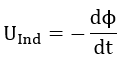
The eddy current testing method is a nondestructive evaluation method. It is widely used for crack detection as cracks cause very large local conductivity changes. However, there are many other applications in which highly sensitive and spatially resolved conductivity analysis can help to solve various inspection tasks. The basic principle is shown below.
Non-contact testing solution for different applications:

Since the sensitivity of eddy current inspection depends on the eddy current density at the defect location, it is important to consider the strength of the induced eddy currents at the defect location. Typically, a setup / frequency / sensor is selected which places the expected defect within a one standard penetration depth. This assures that the strength of the eddy currents would be sufficient to produce a flaw indication.
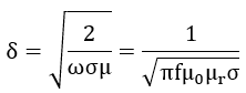
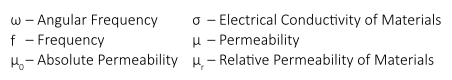
Penetration depth depends on to the permeability, conductivity of the material as well as the frequency.
The standard penetration depth is a term that is relevant to select a good testing setup for the characterization bulk materials. The depth that eddy currents penetrate into a material is affected by the frequency of the alternating current, the electrical conductivity and magnetic permeability of the sample. The depth of penetration decreases with increasing frequency and increasing conductivity and magnetic permeability. The depth at which eddy current density has decreased to 1/e, or about 37% of the surface density, is called the standard depth of penetration (d or 1d) and is used as criteria of ideal measurement for the investigation of bulk materials. At three standard depth of penetration (3d), the eddy current density is down to only 5% of the surface density. So, defects or variation in deeper depth than this do not add recognizable to the measurement effect and therefore those are hardly detectable. Thus, a setup that achieves a standard penetration depth suitable (1d) to the depth of the characteristics of interest enables the best testing result. SURAGUS offers a wide range of sensors with different frequency ranges for optimum testing of materials with different properties.
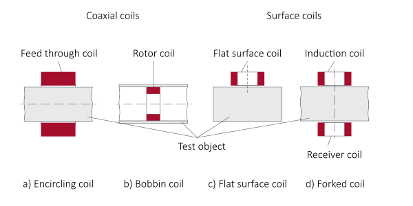
At a given frequency and position the eddy current value is at P0. When bringing a sample into the field or moving it to a different location the complex value shifts towards P1.
Capacitive and resistive effects can be separated by interpreting the data. For example by projecting on x- or y-axis.
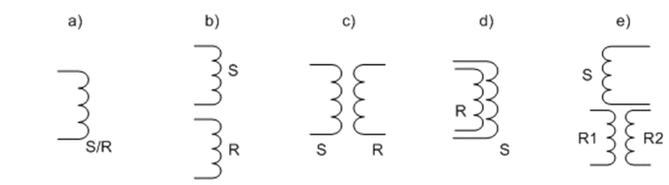
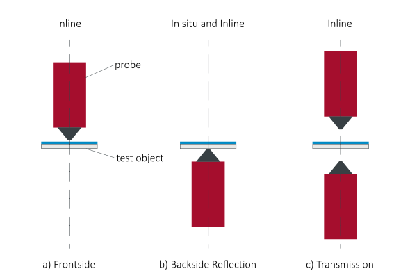
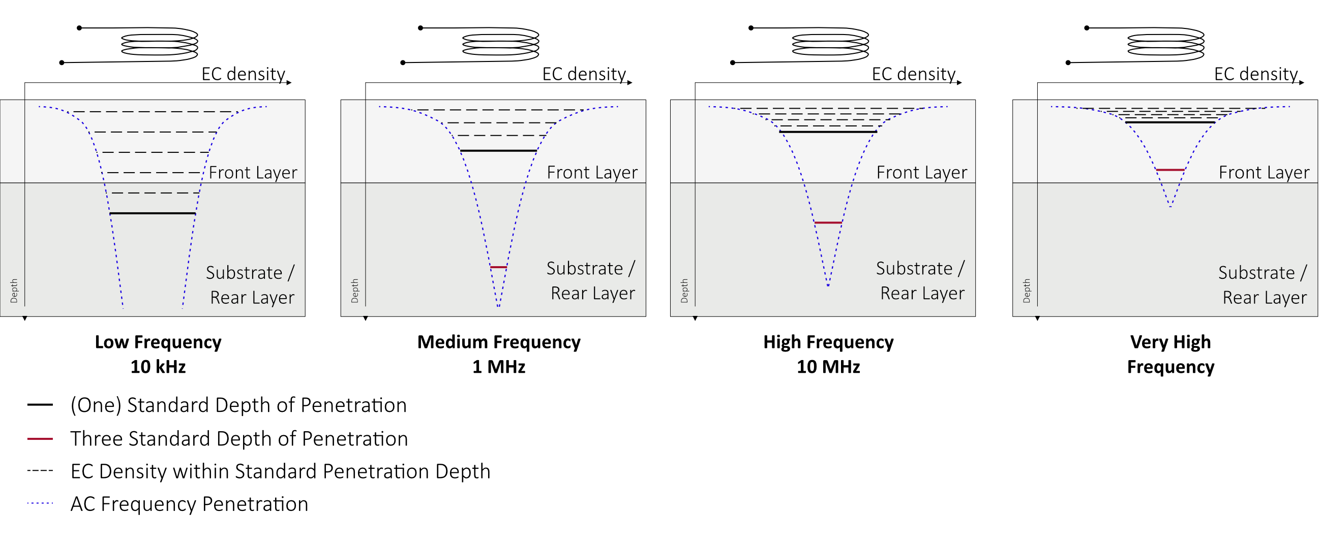
Eddy current measurement setups include single-sided and double-sided setups. Both are widely used but there are advantages and disadvantages to each approach.
Double side transmission mode sensors and tools operate in large distances to the wafer and excel with high tolerance to vertical wafer surface positions. This means the same set can be used for immediate measurement of thin and thick wafers without requiring time consuming set up changes. With large sensor elements gaps up to 100 mm makes double sided transmission ideal for robot handling and the integration into process tools without requiring additional tool space or processing time.
Reflection mode (single side resp. frontside or backside) tools are best for small spot sizes down to 1 mm. The tradeoff is that precise distance control and comes with limitations in sensitivity. This enables penetration depth modification, which allows focusing on resistivity measurements to the surface regions of SiC, GaAs and Si materials on ingot and boule level.
Flexibility in the frequency range supports wide measurement range setups enabling the measurement over 6 decades with the same setup
| 4-point-probe testing | Non-contact eddy current testing |
|---|---|
|
|
|
|
|
|
|
|
|
|
For product requests contact us by using the