Four Point Probe Measurement Method
The four point method is also known as four point measurement. It is a method to measure the sheet resistance. The sheet resistance is the electrical resistance of a surface or a layer. It is defined by the resistivity of the layer divided by its thickness. The most common method for sheet resistance measurement is the four point probe method. This method uses a line of four probes with equal spacing arrayed in a line. A current flows between the two outer probes, resulting in a reduction of the voltage between the two inner probes. By measuring this voltage change, the sheet resistance can then be calculated.
If you want to know more about sheet resistance, click here. If you want to calculate the sheet resistance, click here.
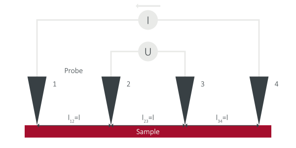
Principle of the Four Point Probe Method
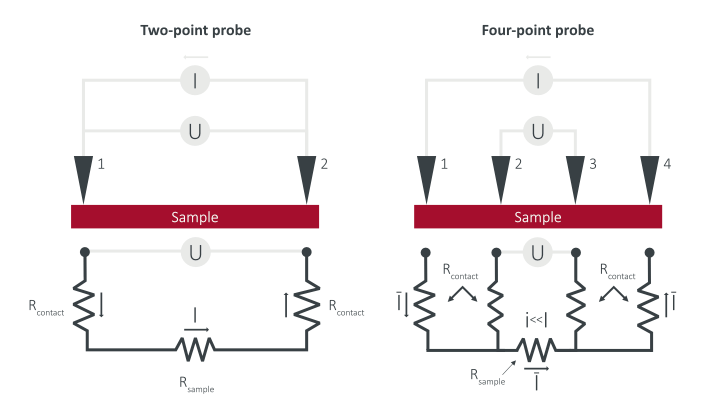
As described before, four-probe measurement works by contacting four equally-spaced probes to a conductive surface. Between probe 1 and 4 a current is applied. Then the voltage between probe 2 and 3 drops and is measured. With the known values for U and I, the sheet resistance can be calculated.
- R□ is the sheet resistance
- ΔU is the change in voltage between probe 2 and 3
- I is the current applied between the outer probes.
The unit Ω is the mathematically correct one, but to make a distinction to the bulk resistance the unit Ω/□ or also “ohm per square” is used.
If the thickness and sheet resistance of the measured material known, the resistivity can be calculated with:
- ρ is the resistivity
- d is the thickness of the material.
Four measuring probes with the same spacing are placed in a row on the surface, with a known current flowing between the two outer ones and the potential difference, i.e. the electrical voltage between these probes, being measured using the two inner probes. Since the method is based on the principle of four-wire measurement, it is largely independent of the contact resistance between the measuring tips and the surface (Thomson bridge principle). The closer the tips come to the edge of the sample, the more the measurement is distorted: the electric current lines cannot propagate freely, they must flow parallel to the edge of the sample.
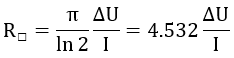
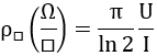
If adjacent measuring probes each have the same distance, the sheet resistance R□ is obtained from the measured voltage U and current I with:
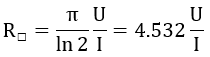
When the current is set to 4.53 mA, the resistivity is simply the voltage reading in mV.
However, this formula is only valid in the ideal case of a very thin (compared to the probes distance), infinitely extended surface with homogeneous resistance behavior.
- The layer thickness must be much smaller than the distance between the probes. (typically 1 mm)
- The total area of the layer must be (infinitely) large compared to the distance between the probes.
- The substrate must be electrically insulating so that the current flows only through the layer. (In the case of semiconductor wafers, this condition is also fulfilled if the layer and the substrate are doped in opposite directions, since the boundary layer then serves as an insulator).
Four-point measurements are used, for example, in semiconductor technology to determine the sheet resistance of a layer deposited on the semiconductor, but in the process the layer can be damaged by the measuring tips.
A method to measure the resistance or sheet resistance without using a sensor array with equal distance is the van der Pauw Method.
Typical Measurement Results of a 4 Point Probe Mapping Tool In Comparison to an Eddy Current Tool
A typical measurement result from a 4PP mapping tool consists of 9 to 49 points. The primary data source for the map includes 9 measured points, while the rest is generated through interpolation. This creates a visually distinguishable map but does not provide additional information beyond the measured data.
The eddy current method, on the other hand, natively records >20,000 measuring points. This results in a high level of detail, whereby every sample information is displayed.
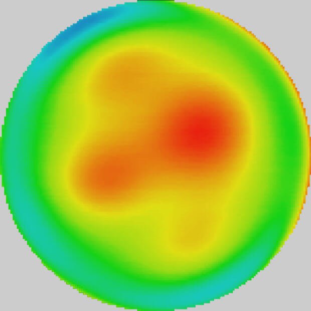
Eddy Current Imaging
This eddy current representation is based on 22,000 measurement points and has not been artificially smoothed through extrapolation. It has a far higher level of detail than a map derived from fewer than 200 measurement points.
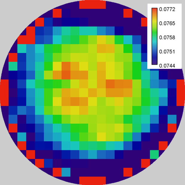
Four Point Probe Map
This map is based on approximately 150 real measurement points and displays the raw data without any extrapolation to create a sharper or smoother gradient. This is the actual information.
Four Point Probe vs Eddy Current Measurement Comparison
Is there a difference in sheet resistance measured with 4PP or Eddy Current?
There is no difference in sheet resistance measured with 4PP or Eddy Current. Both testing methods measure the sheet resistance as a physical property. This property is independent from its measurement method.
What is the advantage of non-contact sheet resistance measurement over common four-point-probe devices?
SURAGUS non-contact measurement solutions allow accurate measurement without impacts due to inhomogeneous contact quality, without damaging any sensitive surfaces or inducing artifacts due to contacting. Furthermore, it allows the accurate measurement of inaccessibly buried or encapsulated layers.
Applying SURAGUS non-contact technology, there is no wear of needles / tips, which typically causes high replacement costs in common 4-point-probe mapping systems. A further significant advantage is the short measurement time: SURAGUS TF Series devices take only a few milliseconds for each measurement and no time for contacting the sample is needed.
This also allows to measure inline during production or “on the fly” in mapping systems. In result, the SURAGUS sheet resistance mapping systems measure thousands of positions in a couple of seconds. No interpolation between measurements points – as typical in 4-point-probe mapping systems – is required. In result defects and non-uniform areas are not missed.
Does roughness affect the measurement quality?
No, other than for contacting measurement technologies, roughness of the layer does not affect the quality or accuracy of the SURAGUS non-contact measurement. SURAGUS non-contact devices are commonly applied with good results for measuring rough or sensitive layers.
Is the system applicable to multilayer systems?
SURAGUS EddyCus® series devices measure through the complete stack of all layers. Multiple conductive films in one stack electrically behave as parallel resistors and can be separated accordingly using standard formulas. Hence, multiple conductive layers can be separated by measuring after each coating step.
What is the measurement pitch / measuring point distance for inline or mapping solutions?
Inline measurements and mapping systems use a lateral measuring point distance of 250 microns to 10 mm (400 mil) depending on the application. The standard distance for property imaging is 1 mm.
What is the spot size of a system?
The sensitivity of the measurement system is highest in the center of the sensor and decreases towards the outside and then no longer contributes to the characterization. The high sensitive zone (HSZ) of sheet resistance measuring systems ranges from 5 to 25 mm depending on the setup. Some systems with 100 mm HSZ were realized for wide coverage in the past as well. This HSZ diameter is primarily defined by the distance to the sample and some sensor characteristics. Smaller distances and sheet resistances enable smaller measurement spot sizes.
Structure and defect monitoring systems utilize a HSZ from 0.5 to 5 mm. Additionally, differential sensors with very high sensitivities are used for the detection of local defects and variations.
What is the spatial resolution?
The spatial resolution is determined by the contrast of the measuring effect, the measurement point distance and the spot size. For example, a wafer mapping can be obtained using a distance (gap) of 2 mm. The high sensitive zone (HSZ) then has a diameter of about 5 mm. Sheet resistance fluctuations of 4% can be measured when affecting about 25% of the 5 mm HSZ. Defects that cause a higher contrast can be detected when affecting smaller areas. For instance, cracks with only a few microns width can be easily detected as the contrast and measurement effect is very high.
Do I need to change several sensors to cover a large measurement range?
The measurement range of one sensor covers 6 decades of sheet resistance. The required measurement range requested by the application is set during manufacturing of the device. There is no need for sensor changes or system adjustments.
Do I have to consider an "edge effect"?
The eddy current-based measurement relies on an induced electric current in conductive layers. The currents have a high current density below the sensor that diminishes with increasing distance to the sensor. This effect is also known from 4PP systems, which use the similar physics and cope with the same effect. Typically, there is a correction formula deepening on the distance to the edge in the user manual of 4PP and Eddy Current systems so the user can correct those measurements by multiplying a factor.
SURAGUS mapping devices provide an integrated and automated correction of this “edge effect” for many pre-configured sample sizes and allow an accurate measurement at any position of the sample.
Do vibrations of the sample have an influence on the measurement?
Depending on the measuring range and the measuring gap different vibrations can be tolerated. The standard tolerance is ± 1 mm. A low sheet resistance and large measuring gap allow tolerating large variances of up to ± 5 mm. For the measurement of curved substrates sensors are used with integrated ultrasonic sensors, the measured values are compensated according to the position in the measuring gap and position-independent accurate measurement values can be determined.
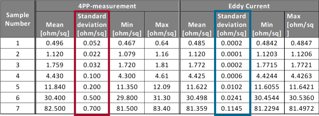
More Precise Conclusions Through Eddy Current in Comparison to the Use Of 4 Point Probe Measurements
Four point probe measurements have some significant limitations:
- Small errors are overlooked due to interpolation
- Effects at the edge of a wafer cannot be detected
- The repeatability for thick metal layers is significantly better with the eddy current method
Measurement Duration Comparison Non-contact Eddy Current Metrology vs 4 Point Probe
| Kind of device | 4-Point-Probe | Eddy Current Technology |
| Single point | 20 measurements per min | 60 measurements per min |
| Mapping device | 120 measurements per min | 2,000 measurements per min |
| Automated Mapping System | 120 measurements per min | 16,500 measurements per min |
When to Use Eddy Current Methode and When to Use Four Point Probe Methode?
| When to use eddy current technology | When to use four point probe |
| For very flat and hard surface such as SiC | Conductive coating combined with a conductive substrate |
| For samples with a non conductive top layer and a conductive encaspulated layer | Price is most important |
| For samples with less than 100 mOhm/sq | |
| If you want to measure on production wafers not only test wafers | |
| For fluttering production lines | |
| For close to the edge measurements | |
| For curved or rough samples | |
| For inline measurements |
AI will be used more and more in the future to improve throughput, resource efficiency and product quality. This requires a reliable data basis. If the production line is to be automated, a large number of sensors are needed to continuously record data and measure quality after as many production steps as possible.
Four Point Probe Limitations
Four point probe measurement have to handle with a few problems:
- Due to the contact-based measurement, samples can be damaged
- To get the best measurement results, the probe must be placed in the center of the sample
- You always need a non-conductive layer under the layer to be measured
- The measurement result always depends on the shape of the sample. There are different correction factors for different shapes. But not only the shape, but also the size and the thickness of the sample are important and need different correction factors
Four Point Probe Measurement
Again, the sheet resistance is the result of dividing the resistivity (ρ) of a layer through the layers thickness (d).

Four Point Probe Measurement of Thin Films
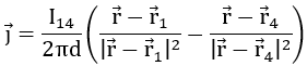
If the current flows through the contacts into the layer under investigation with a uniform resistivity, then the current spreads out in a circle. The current density can be given by:

The current is induced at location r1 and drawn at location r4. This produces a typical dipole pattern. For the thin film approximation, the distance between the peaks must be much larger than the thickness of the thin film. Then the current density can be given by:
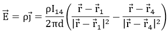
The electric field is:
The measured voltage between r2 und r3 is:
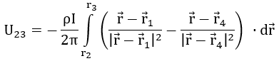
The voltage is independend of the path:

The voltage after integration is:
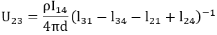
with:
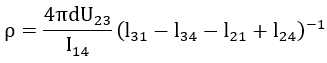
The resistivity is:
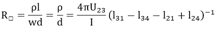
If the thickness of the layer is unknown, then the resistance cannot be calculated. In this case, the sheet resistance can be given by:
Four Point Probe Measurement of Thin Films
The is no difference in measuring the bulk resistivity and the sheet resistivity. The only difference: By using the layer thickness (d in cm) the resistivity is reported in cm-3. The following formula can only be used if the layer thickness is less than half of the probe spacing (d < l/2).
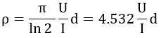
For layer thickness greater than half the probe spacing, the following formula can be used:
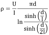
l is the probe spacing.
Four Point Probe Measurement of Sheet Resistivity
Using the voltage and current readings from the probe:
With:
Two Point Probe Resistivity Measurement
Contact and propagation resistance are very high when using two-point probes. This means that the resistance of the sample cannot be isolated. This is the advantage of the four-point method. The contact and propagation resistances of the voltage probes are very low, which makes the measurement accuracy very high. This is because two wires are used, one to induce the current and the other to measure the drop in voltage.The be clear: a two point probe measures the combined resistivity of the sample, the contact resistance and the probe resistance whereas a four-point probe only measures the sample resistivity.
More Precise Alternative to 4PP Measurement – Eddy Current Measurement
- Suitable for inline measurement
- High quality mappings with up to 1 million measurement points per sample
- No contamination or destruction of the surface, because of non-contact measurement
- Able to characterize even hidden layers
However, the eddy current method not only enables faster measurements, but also more reliable measurements. The repeatability of the eddy current measurement significantly exceeds the repeatability of the 4PP measurement.
When the eddy current sensors are calibrated to the measurement range of the samples, this leads to much more accurate measurement results than with the 4PP method.